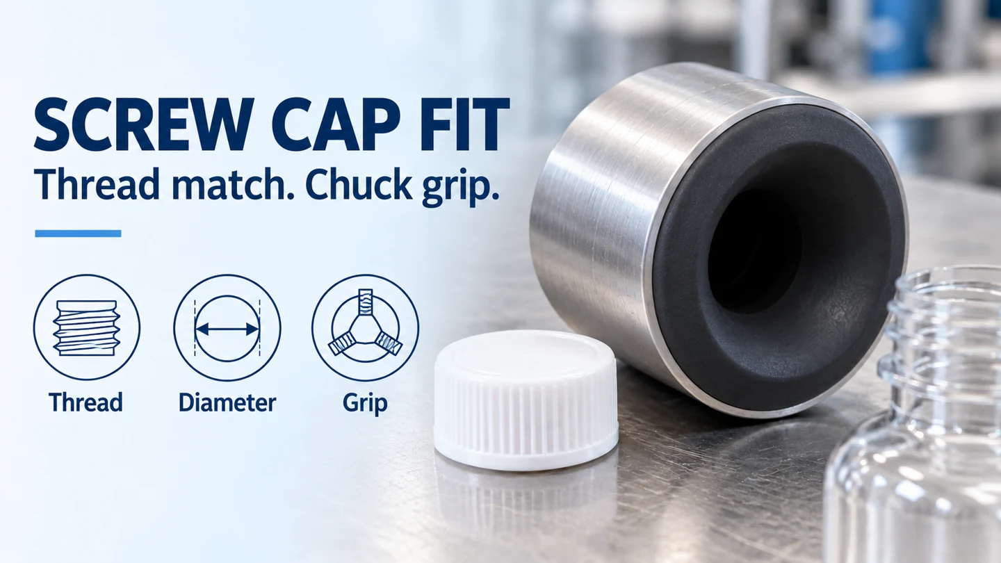
A screw cap needs two separate fit checks: its internal thread must mate with the bottle neck, and its outside surface must engage the capping chuck. Select the chuck from the cap’s measured outside grip diameter, surface profile and usable contact height, then verify tightening and release with the cap-and-bottle combination.
For a pre-threaded plastic or metal closure, a matching neck-finish designation starts the thread check. The chuck specification follows from the cap’s exterior geometry. Use the sequence below when ordering change parts, replacing an insert or investigating a cap that fits by hand but slips during machine application. Roll-on pilfer-proof closures use roller forming; the capping machinery guide explains that equipment distinction.
| Selection input | What to record | Decision it supports |
|---|---|---|
| Cap and bottle thread | Full finish designation and drawing revisions | Mating thread and engagement |
| Cap outside diameter | Measured grip-zone OD and drawing limits, in mm | Candidate insert cap range |
| External surface | Smooth wall, ribs or serrations; material and finish | Friction insert or profile-matched tooling |
| Contact geometry | Usable skirt height, top shape and adjacent band/shoulder clearances | Engagement and release |
| Package and machine | Bottle restraint, chuck interface and specified torque criteria | Sample trial and tooling approval |
Check the screw cap thread and bottle finish first
Confirm the full finish designation, compare the drawings and inspect sample engagement before adjusting the chuck. A cap that starts crooked or binds on the bottle presents a different problem from a chuck slipping over a correctly engaged cap.
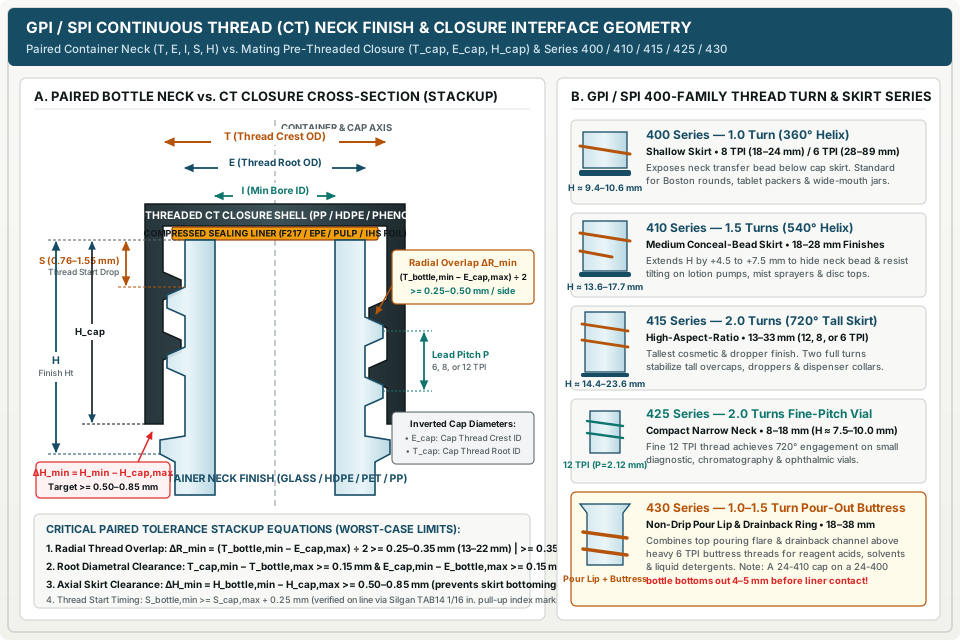
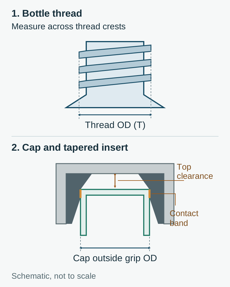
SKS Bottle & Packaging’s Cap and Neck Finishes identifies T as the bottle thread’s outside diameter and S as the distance from the top of the finish to the start of the thread. These dimensions affect mating and engagement. Check the closure drawing against the bottle drawing, including the sealing arrangement, and compare actual samples with the approved pair.
Turn sample caps onto their intended bottles to check that they start squarely and seat as expected. Treat this as an initial fit check; package approval also needs the specified sealing and torque checks. If the behavior changes between component lots, investigate the components as well as the machine. Frain Industries’ Solving Common Capper Problems describes how cap and neck dimensional variation can change the fit and resulting torque.
The bottle neck finishes guide provides the broader compatibility workflow. For finish-code terminology and dimension locations, use the continuous-thread closure reference alongside the controlled supplier drawings.
Measure the cap where the chuck will grip
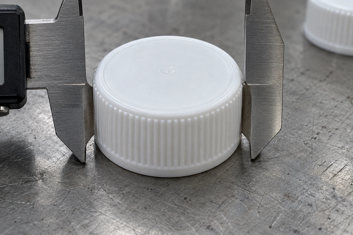
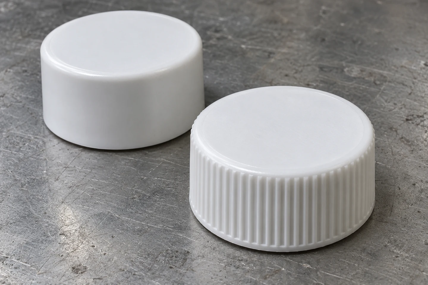
Measure across the cap’s actual contact surface. On a ribbed cap, the rib crests form the external envelope presented to the chuck. A nominal neck size describes a different interface.
Swan-Matic’s How to Choose the Right Bottle Capping Chuck Insert Material and Size emphasizes actual cap diameter in insert selection. To turn that input into a useful tooling request:
- Identify the intended grip zone on the cap drawing and sample. Note whether it is straight, tapered, smooth or ribbed.
- Measure outside diameter at that zone, keeping the measuring faces square to the cap and avoiding distortion of the skirt.
- Repeat around the cap and across representative samples. Record the observed minimum and maximum alongside the drawing tolerance and lot identification.
- Record the available contact height and the features that bound it: the top radius, a tamper-evident band, a flange or the bottle shoulder.
This measurement record helps distinguish a diameter issue from insufficient contact height or a change in rib geometry. For a profile-matched chuck, include the serration detail or an approved physical cap sample with the OD record.
Select the insert range and grip profile together
Use the chuck manufacturer’s published cap range to shortlist tooling, then check its contact geometry with samples. Overlapping ranges make diameter a selection input rather than a unique part number.
For example, Swan-Matic’s Insert and Driver Shell Sizing Charts lists the following cap ranges:
| Swan-Matic insert number | Published cap range (mm) |
|---|---|
| 20 | 12–24 |
| 25 | 18–28 |
| 30 | 22–33 |
| 40 | 25–41 |
For that insert family, Swan-Matic advises choosing the next larger insert and shell when the measured cap diameter is close to the upper cap-range limit. It also recommends cap-and-bottle samples for the final selection. Keep the chart’s fields separate: the insert number identifies the part; the cap range describes supported cap diameters; the insert’s physical dimensions are a separate drawing.
The grip mechanism then determines what “fit” means:
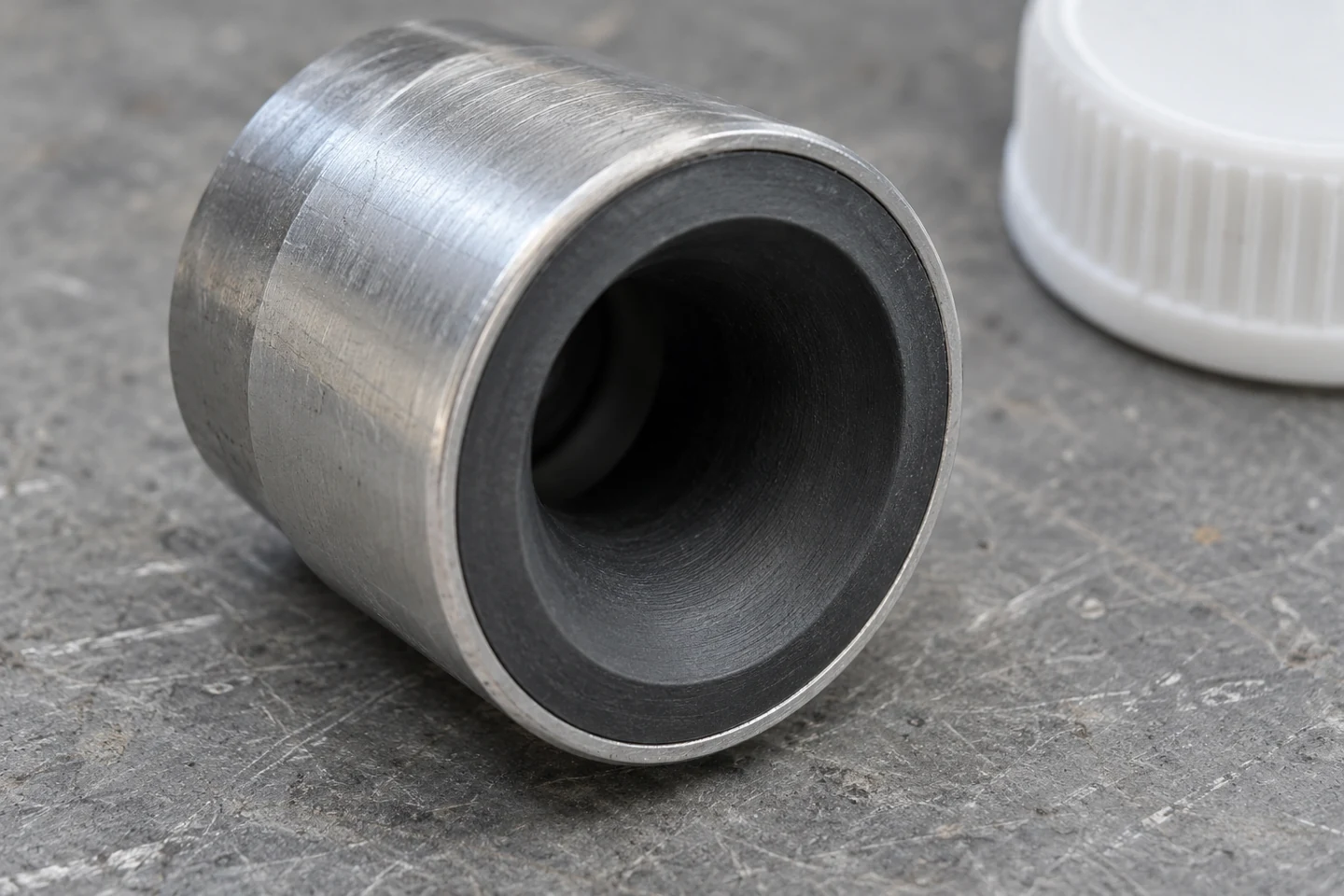
- Tapered elastomer insert: the cap enters a compliant tapered opening. Contact and transmitted torque depend on the insert material, surface condition and axial engagement. Frain describes slippage when engagement/downforce is insufficient, including cases where the bottle deforms under load.
- Matched serrated chuck: tooling features engage the cap’s external serrations. Match the pattern as well as the overall diameter. Frain notes that changing cap serrations requires changing the chuck or its serrated insert.
Specify the chuck’s grip geometry and contact position before assigning an internal diameter. For tapered tooling, an opening measurement alone leaves the contact depth unresolved. For serrated tooling, a diameter alone leaves the mating profile unresolved.
Match insert material to the cap surface
Choose material for grip and acceptable cap appearance, then evaluate it with the intended closure. Hardness is one specification within that choice: Shore A measures indentation response, while wear, marking and grip also depend on the compound and contact conditions.
The APEX Econo Inline Chuck Capper Operations Manual, version 1.1, section 4.11, gives these standard insert options for its equipment:
| APEX insert material | Standard hardness (Shore A) | Selection consideration in the manual |
|---|---|---|
| Polyurethane | 45–55 | Wear resistance and low residue |
| Vinyl | 45–55 | Smooth contact surfaces; an option when polyurethane slips |
| White rubber | 50–60 | Smooth surfaces or minor serrations; light-cap marking considerations |
| Black rubber | 60–70 | Dark-colored caps |
| Tan rubber | 70–80 | Serrated metal caps or abrasive applications |
Use this as an APEX material-selection example. Its material options and the Swan-Matic size chart describe their respective tooling systems. Order the insert material, geometry and driver shell as a compatible set from the selected equipment supplier.
When comparing candidates, inspect the cap after tightening for scuffing, transferred residue and rib damage. Also observe release: acceptable grip during tightening must be followed by clean disengagement. Retain the cap’s material, color and surface finish in the trial record so a later component change can be assessed against the approved combination.
Diagnose slipping, marking and poor release
Locate where relative motion occurs before changing the torque setting. The chuck can slip on the cap, the bottle can turn in its restraint, or the torque-control mechanism can operate incorrectly. Each requires a different check.
APEX’s troubleshooting section lists insert wear, capper assembly height and torque setting among the checks for low torque. Frain explains that cap-to-insert slip can determine the tightening result before the intended torque control takes effect, while also scuffing the cap. Its bottle-holding guidance also calls for preventing bottle rotation without deforming the container. Use the machine’s safe observation procedure; isolate power and air as required by its manual before mechanical inspection or adjustment.
| Observed symptom | First checks | What to verify in the next trial |
|---|---|---|
| Cap slips late in tightening | Insert wear, cap-range selection, material, contact position and bottle restraint | Torque control operates as intended while the cap remains securely engaged |
| Scuffs, residue or rib damage | Contact surface, insert condition, profile match and engagement | Cap appearance meets the agreed acceptance criteria |
| Bottle turns or deforms | Restraint contact and package support | Bottle remains restrained without unacceptable deformation |
| Cap starts crooked or binds | Thread pair, component variation and cap placement | Square engagement and expected seating with approved components |
| Cap catches as the head retracts | Contact depth, profile and nearby band/flange clearance | Clean release throughout the approved component range |
Record the initial condition and each adjustment separately. Raising torque or increasing engagement without identifying the slipping interface can leave the underlying fit problem in place. Confirm the torque measurement method and conditions before treating variation in readings as a machine fault; the closure torque guide explains the distinction between application and removal measurements.
Prepare drawings and samples for tooling approval
Send a defined cap-and-bottle combination with its measurement record. A supplier can assess tooling more directly when the request includes the external grip geometry as well as the neck-finish designation.
Prepare one package containing:
- Cap and bottle drawings: part numbers, revisions, full finish designation, thread and sealing details, plus external cap geometry and tolerances.
- Grip measurements and samples: observed cap OD range, measurement height, rib/serration profile, usable contact height, cap material/finish and representative cap-and-bottle lots.
- Machine interface: capper identification, driver/chuck connection, current tooling details and bottle restraint arrangement.
- Acceptance criteria: specified application and removal torque requirements with their measurement conditions, package sealing checks, permitted surface marks and release requirements.
Agree the trial quantity and acceptance limits before the trial. Evaluate tightening, cap appearance, bottle condition and release together, including representative component variation. Retain the approved cap/bottle revisions, insert and shell part numbers, material, settings and acceptance results as the reference for subsequent changeovers.
Technical references
- SKS Bottle & Packaging: Cap and Neck Finishes — finish designation and T/S dimension definitions.
- Swan-Matic: Insert and Driver Shell Sizing Charts; How to Choose the Right Bottle Capping Chuck Insert Material and Size — actual cap diameter, range selection and material considerations.
- APEX Filling Systems: Econo Inline Chuck Capper Operations Manual, v1.1, sections 4.11 and 6.2 — insert materials, hardness and troubleshooting.
- Frain Industries: Solving Common Capper Problems, “Bottles and caps,” “Chucks” and “Bottle holding” — component variation, grip mechanisms and restraint.
- Lancing Screw Cappers: Choosing Cap Chucks and Change Parts — contact profile, depth, release and tooling approval criteria.