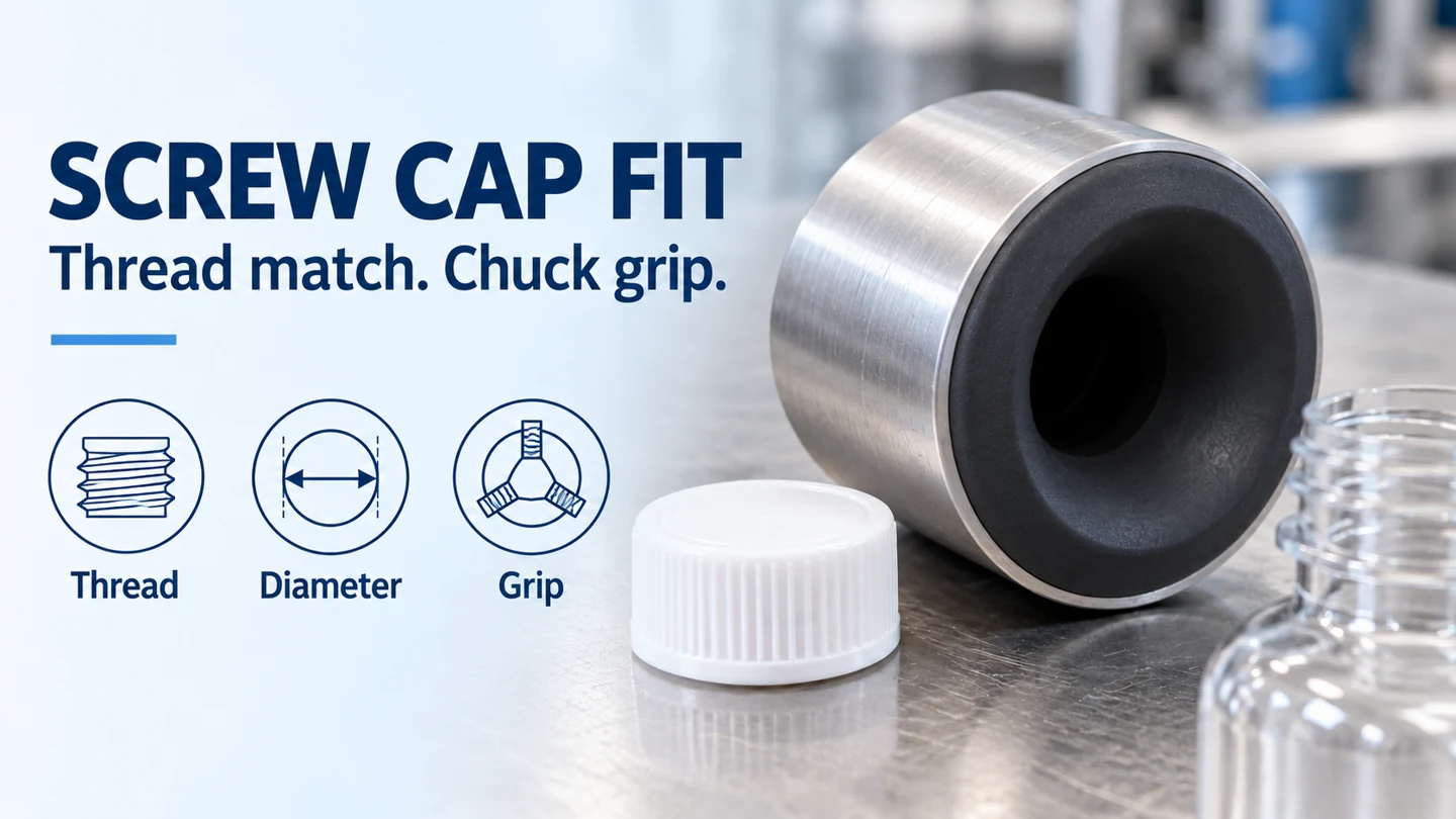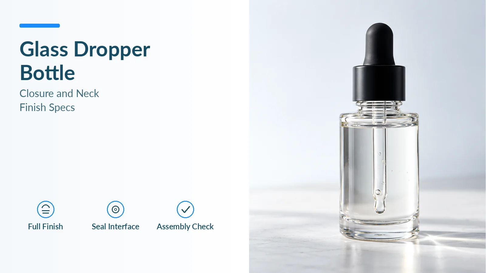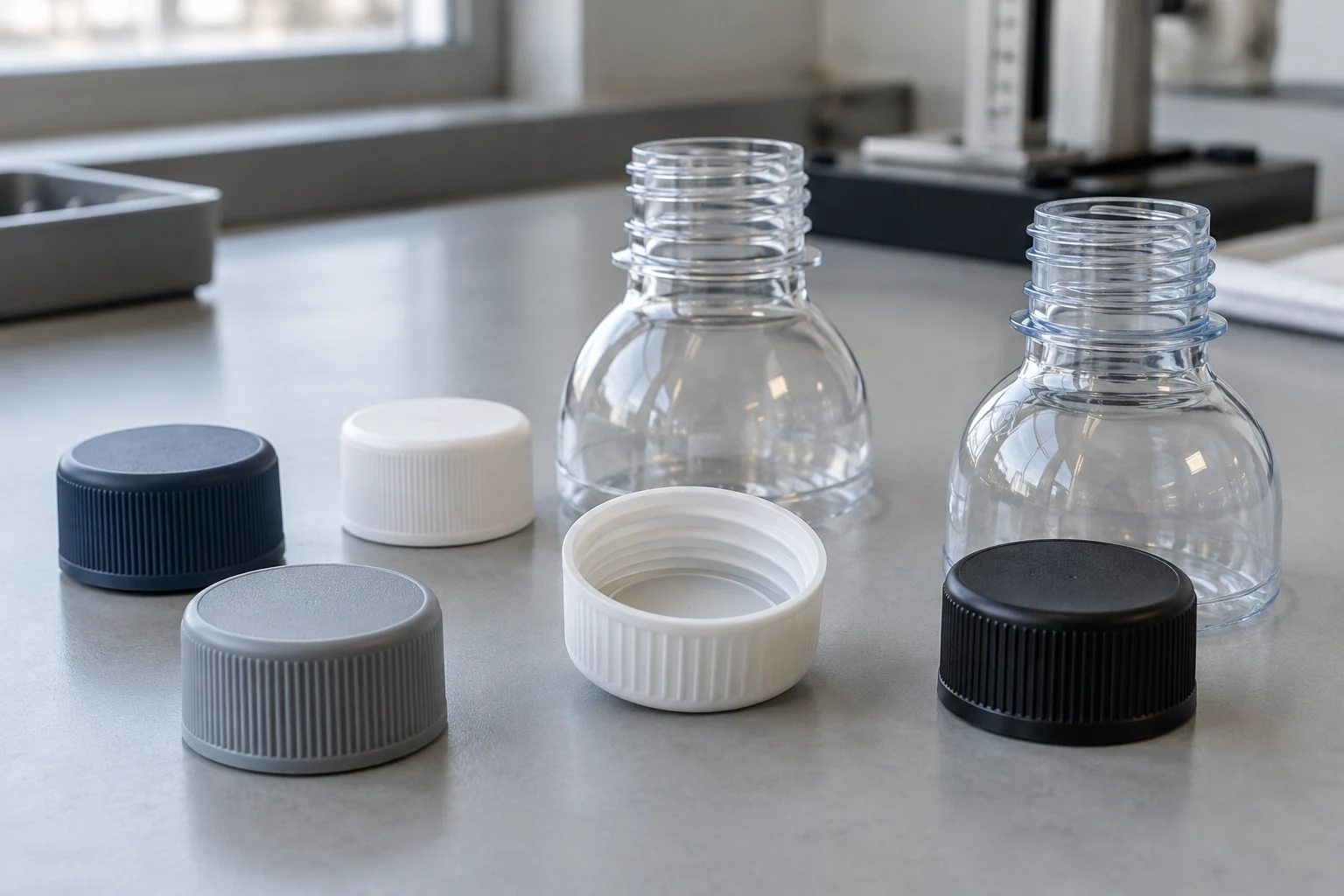
Specifying a continuous thread closure (CT closure) by nominal diameter alone—such as ordering a “24 mm cap” or assuming a 24-410 dispensing closure will seal on a 24-400 container—is one of the most frequent root causes of bottling-line leaks, skirt bottoming-out, and thread stripping. Under the dimensional standards established by the Glass Packaging Institute (GPI) and the Plastics Industry Association (SPI / ISBT), a ct closure neck finish only achieves hermetic liner compression when five container neck coordinates (T, E, I, S, and H) and four inverted closure coordinates (T_cap, E_cap, H_cap, and S_cap) maintain positive radial thread overlap (ΔR_min >= 0.25–0.50 mm per side) and positive axial skirt-to-shoulder clearance (ΔH_min >= 0.50–0.85 mm) across worst-case manufacturing tolerances.
Within our bottle neck finishes section, our supporting pillar on bottle neck finish compatibility establishes the paired drawing review workflow and lot-traceable sample retention rules. This engineering reference provides the numeric gpi thread finish 400 410 415, 425, and 430 series specifications, standard T / E / I / H / S tolerance tables from 15-425 to 38-400, worst-case tolerance stackup equations, L-style (30°) versus M-style (10°–15° buttress) flank vector mechanics, and diameter-indexed application and removal torque tables (ASTM D2063 / Silgan TAB14).
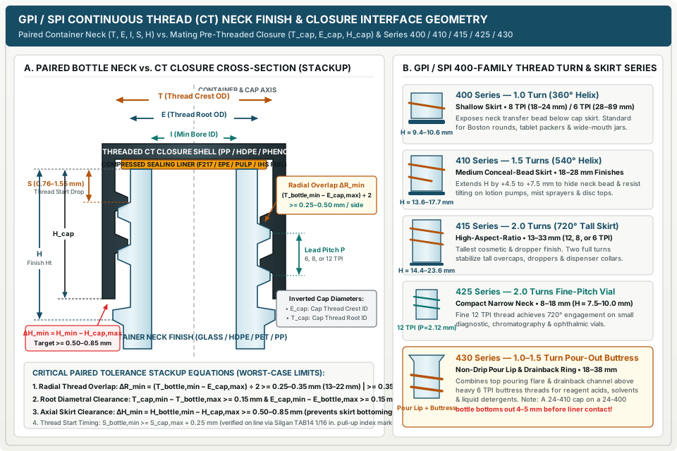
How GPI and SPI continuous thread (CT) finish codes work: 400, 410, 415, 425, and 430
In North American and international rigid packaging, pre-threaded continuous thread closures and their mating glass or plastic bottle necks follow a two-part numeric designation originally codified by the Glass Packaging Institute (GPI, formerly the Glass Container Manufacturers Institute, GCMI) and adopted by the Plastics Industry Association (SPI, formerly the Society of the Plastics Industry) and the International Society of Beverage Technologists (ISBT).
As documented in TricorBraun’s Anatomy of a Bottle Neck Finish, Berlin Packaging’s Neck Finish Guide, and Paramount Global’s Bottle Neck Thread Finish Guide, every standard CT finish code is written as XX-YYY (using a hyphen for glass/rigid container drawings, such as 24-410 or 28-400) or XX/YYY (using a slash in dispensing pump and closure catalogs, such as 24/410 or 18/415):
- First Number (
XX— Nominal Outer Thread Diameter inmm): Indicates the approximate outer diameter in millimeters measured across the outermost crests of the bottle threads (Tdimension). Because historical GPI/SPI drawing masters were standardized in decimal inches (in.), the actual controlledTdimension is slightly smaller than the nominal integer—for example, a28-400neck has a controlledTrange of27.13–27.64 mm(27.38 ± 0.25 mm/1.078 ± 0.010 in.), and a38-400neck has a controlledTrange of37.19–37.80 mm(37.49 ± 0.30 mm/1.476 ± 0.012 in.). - Second Number (
YYY— GPI/SPI 400-Family Thread Turn & Skirt Depth Series): A three-digit series code in the400family (Continuous Thread) that dictates the number of continuous helical thread turns, the thread pitch (TPI/ axial leadP), the vertical finish height (H), and whether the closure skirt leaves the lower neck transfer bead exposed or concealed.
While unthreaded aluminum closures are cold-formed onto CETIE BVS or GPI 1650/1655 finishes by 4-roller sealing heads (covered in our ROPP capper head adjustment guide), pre-threaded 400-family CT closures arrive at the capping turret with injection-molded (PP, HDPE, ABS) or compression-molded (thermoset phenolic / urea) internal threads ready for rotational tightening. The table below compares the five primary gpi thread finish 400 410 415, 425, and 430 series.
| GPI / SPI Series Code | Helical Thread Engagement Turns | Vertical Finish Height (H) & Skirt Profile |
Standard Thread Pitch (TPI & Lead P) |
Standard Nominal Diameter Range (XX) |
Primary Structural Function & Packaging Applications |
|---|---|---|---|---|---|
400 Series (GPI/SPI 400) |
1.0 full turn (360° helical contact) |
Shallow / Short Skirt (H = 9.40–10.64 mm / 0.370–0.419 in. across 18–38 mm) |
8 TPI (P = 3.18 mm) for 18–24 mm; 6 TPI (P = 4.23 mm) for 28–89 mm |
18 mm to 120 mm (18-400, 20-400, 24-400, 28-400, 33-400, 38-400, 53-400, 70-400, 89-400) |
Baseline general-purpose CT finish. Leaves the container neck transfer bead/support ring exposed below the cap skirt. Minimizes closure resin weight and unscrewing revolutions on Boston rounds, OTC tablet packers, wide-mouth food jars, and industrial containers. |
410 Series (GPI/SPI 410) |
1.5 turns (540° helical contact) |
Medium / Conceal-Bead Skirt (H = 13.61–17.73 mm / 0.536–0.698 in. across 18–28 mm) |
8 TPI (P = 3.18 mm) for 18–24 mm; 6 TPI (P = 4.23 mm) for 28 mm |
18 mm to 28 mm (18-410, 20-410, 22-410, 24-410, 28-410) |
Adds +0.5 thread turn and extends neck height H by +4.5 to +7.5 mm over the 400 series so the closure skirt conceals the neck transfer bead. Provides 50% more thread bearing length to resist lateral cocking on lotion pump dispensers, fine-mist sprayers, trigger sprayers, and disc-top caps. |
415 Series (GPI/SPI 415) |
2.0 full turns (720° helical contact) |
Tall / High-Aspect-Ratio Skirt (H = 14.35–23.55 mm / 0.565–0.927 in. across 13–28 mm) |
12 TPI (P = 2.12 mm) for 13–15 mm; 8 TPI (P = 3.18 mm) for 18–24 mm; 6 TPI (P = 4.23 mm) for 28 mm |
13 mm to 33 mm (13-415, 15-415, 18-415, 20-415, 24-415, 28-415) |
Tallest standard cosmetic and specialty dispensing finish. Two full 360° turns stabilize high-collar treatment pumps, glass dropper assemblies, mascara/lip-gloss wands, and tall cylindrical overcaps against off-axis bending loads. |
425 Series (GPI/SPI 425) |
2.0 full turns (720° fine-pitch contact) |
Compact Narrow-Neck Vial Skirt (H = 7.54–10.03 mm / 0.297–0.395 in.) |
12 TPI (P = 2.12 mm / 0.083 in.) fine-pitch thread across all sizes |
8 mm to 18 mm (8-425, 10-425, 13-425, 15-425, 18-425) |
Engineered for narrow-diameter diagnostic vials, chromatography autosampler vials, ophthalmic dropper bottles, and reagent vials where a coarse 8 TPI pitch would consume excessive vertical height or thin out the neck root wall. Packs 2.0 full turns into a compact 7.5–10.0 mm finish height. |
430 Series (GPI/SPI 430) |
1.0 to 1.5 turns (heavy buttress contact) |
Tall Pour-Lip & Drainback Skirt (H = 16.51–25.40 mm / 0.650–1.000 in.) |
6 TPI (P = 4.23 mm / 0.167 in.) deep asymmetric buttress thread |
18 mm to 38 mm (18-430, 24-430, 28-430, 33-430, 38-430) |
Integrates a sharp upper non-drip pouring flare/lip and an intermediate drainback channel/bead above deep buttress threads. Specified on laboratory acid/solvent bottles, corrosive chemical jugs, liquid laundry detergents, and edible oil containers requiring clean liquid cut-off and high top-load resistance. |
Worked proof: why 24-400 and 24-410 components fail when interchanged
Because both 24-400 and 24-410 finishes share a 24 mm nominal crest diameter (T ≈ 23.62–23.67 mm) and an identical 8 TPI thread pitch (P = 3.18 mm), operators occasionally attempt to substitute one for the other during a packaging component shortage. Evaluating the axial height stackup (H_bottle vs. H_cap) demonstrates why cross-series mating causes immediate production failures:
- Case 1 — Tall
24-410Closure (H_cap = 15.20 mm) applied to a Short24-400Bottle (H_bottle = 10.16 ± 0.38 mm):
As the spindle or chuck capper drives theΔH = H_bottle,nom - H_cap = 10.16 mm - 15.20 mm = -5.04 mm (SEVERE AXIAL INTERFERENCE)24-410closure clockwise down the8 TPIthread helix, the lower rim of the tall closure skirt strikes the bottle shoulder or neck transfer bead5.04 mmbefore the top sealing land of the bottle reaches the closure liner. The capping clutch trips at the target12.0 in-lbs(1.36 N·m) application torque because the skirt is jammed hard against the shoulder, giving quality inspectors a false “tight” torque reading while the liner sits suspended in air with zero sealing compression (100% leaker rate). - Case 2 — Short
24-400Closure (H_cap = 9.10 mm,1.0turn) applied to a Tall24-410Bottle (H_bottle = 16.15 ± 0.33 mm,1.5turns):
Here, the shortΔH = H_bottle,nom - H_cap = 16.15 mm - 9.10 mm = +7.05 mm (EXCESSIVE EXPOSED NECK)24-400closure reaches the top sealing land and compresses its liner, but leaves7.05 mmof bare lower thread helix and the neck transfer bead exposed above the bottle shoulder. Worse, if the24-410bottle thread run-out or lower bead interferes with the short skirt cut-off, or if a high-profile dispenser actuator is mounted in a1.0-turn skirt, lateral actuation loads can cock the closure off the thread start.
Takeaway: Never treat a match in nominal diameter (XX) and pitch (TPI) as proof of compatibility; the three-digit GPI/SPI series suffix (400, 410, 415, 425, 430) controls vertical skirt clearance (H) and helical bearing length, making cross-series substitutions mechanically non-interchangeable.
Critical container neck and CT closure dimensions: T, E, I, S, H, and tolerance stackup
As defined in Drug Plastics’ Neck Finishes Information Sheet, TricorBraun’s dimensional standard guide, and SKS Bottle & Packaging’s measurement protocol, every controlled ct closure neck finish drawing specifies five primary container dimensions alongside four inverted internal closure dimensions (illustrated in Figure 1, Panel A).
The five container neck finish coordinates (T, E, I, S, H)
T(Thread Crest Outside Diameter): The maximum outer diameter measured across the outermost peaks (crests) of the external container threads (mmorin.). Because extrusion-blow-molded (EBM) plastic containers (HDPE,PP,LDPE) develop slight parting-line flash and post-mold crystalline shrinkage ovality, incoming quality inspection must measureTwith a calibrated digital vernier caliper (±0.01 mmresolution) across two perpendicular axes: along the mold parting seam (0°) and perpendicular to the parting seam (90°).E(Thread Root Cylinder Outside Diameter): The outer diameter of the cylindrical neck wall measured at the base of the thread groove (root) between adjacent thread crests. SubtractingEfromTand dividing by two yields the single-side container radial thread depth (h_thread,bottle):
On standardh_thread,bottle = (T_bottle - E_bottle) / 218 mmto24 mmfinishes (8 TPI),h_thread,bottle = 1.07 mm(0.042 in.); on28 mmto38 mmfinishes (6 TPI),h_thread,bottle = 1.19 mm(0.047 in.); on fine-pitch13-425and15-425vials (12 TPI),h_thread,bottle = 0.68 mm(0.0265 in.).I(Minimum Inner Bore Diameter): The minimum unobstructed internal diameter through the full vertical height (H) of the neck bore. While top-land liner seals do not contactI, theIdimension governs three critical packaging interfaces:- Filling nozzle entry clearance: High-speed diving or fixed filling nozzles require
D_nozzle,OD <= I_bottle,min - 1.50 mmto prevent nozzle-to-neck collisions during container indexing. - Bore-seal / plug-seal interference fit: Orifice reducers, Euro dropper inserts, wine stoppers, and linerless bore-plug closures seal radially against
Irather than the top rim; a blow-molded neck with internal parison flash or taper will either split under plug insertion or leak. - Dispensing subassembly passage: Lotion pump dip tubes and valve housings as well as glass dropper pipettes must pass cleanly through
I_minwithout scraping or binding.
- Filling nozzle entry clearance: High-speed diving or fixed filling nozzles require
S(Thread Start Distance): The vertical axial distance measured from the top sealing surface (land / rim) down to the intersection of the upper flank of the first thread start (typically 0.76 to 1.55 mm/0.030 to 0.061 in.). TheSdimension controls the rotational index angle at which the closure threads engage and stops the top closure thread from crashing into the bottle thread start when the liner compresses.H(Neck Finish Height): The total vertical axial distance measured from the top sealing surface (land) down to the lower undercut of the neck transfer bead (support ring) or, on beadless finishes, the plane where theTdiameter cylinder intersects the container shoulder.
Inverted closure dimensions (T_cap, E_cap, H_cap, S_cap) and the 3 stackup equations
On the mating pre-threaded continuous thread closure drawing, radial coordinates are inverted to match the container feature they clear or engage:
T_cap(Closure Thread Root Inside Diameter): The internal diameter of the smooth inner closure skirt wall between internal thread teeth (which surrounds the container’sTthread crest).E_cap(Closure Thread Crest Inside Diameter): The minimum internal diameter measured across the inward-projecting peaks of the closure threads (which projects into the container’sEthread root groove).H_cap(Closure Internal Skirt Depth): The axial distance from the inner face of the uncompressed liner (or linerless sealing ring) to the bottom rim of the closure skirt.S_cap(Closure Thread Start Drop): The axial distance from the inner liner face down to the start of the first internal closure thread crest.
To verify that a bottle lot and closure lot will assemble and seal across their full production tolerance ranges (worst-case stackup), packaging engineers evaluate three fundamental equations:
1. Minimum radial thread engagement (ΔR_min) and root clearance (ΔC_root)
When a closure is torqued onto a bottle, axial clamping load (F_axial) is supported solely by the overlapping radial shelf between the container’s external thread crests (T_bottle) and the closure’s internal thread crests (E_cap). Under worst-case tolerance stackup—combining a bottle molded at its minimum allowable crest diameter (T_bottle,min) with a closure molded at its maximum allowable thread crest inside diameter (E_cap,max)—the single-side minimum radial thread engagement (ΔR_min) is:
ΔR_min = (T_bottle,min - E_cap,max) / 2- Acceptance Thresholds for
ΔR_min:- Narrow-neck finishes (
8–22 mm,12 TPI&8 TPI):ΔR_min >= 0.25 to 0.35 mm(0.010–0.014 in.per side, or>= 0.50–0.70 mmtotal diametral thread interference). - Medium and wide-mouth finishes (
24–89 mm,8 TPI&6 TPI):ΔR_min >= 0.35 to 0.50 mm(0.014–0.020 in.per side, or>= 0.70–1.00 mmtotal diametral thread interference).
- Narrow-neck finishes (
- Simultaneous Diametral Root Clearance Check (
ΔC_root): To prevent the thread crests from binding radially against the opposing root wall before the closure can rotate down onto the liner, worst-case maximum material conditions must maintain at least0.15 mm(0.006 in.) of diametral clearance at both the major and minor diameters:ΔC_major = T_cap,min - T_bottle,max >= 0.15 mm (0.006 in.) ΔC_minor = E_cap,min - E_bottle,max >= 0.15 mm (0.006 in.)
2. Minimum axial skirt-to-shoulder clearance (ΔH_min)
To ensure that 100% of axial clamping force compresses the sealing liner (typically by 15%–30% of uncompressed liner thickness t_liner) rather than bottoming out the lower edge of the closure skirt against the neck bead or bottle shoulder, worst-case axial clearance between the shortest allowable bottle finish (H_bottle,min) and the deepest allowable closure skirt (H_cap,max) must satisfy:
ΔH_min = H_bottle,min - H_cap,max >= 0.50 to 0.85 mm (0.020 to 0.033 in.)When measured after the closure is tightened to nominal application torque (compressing a 0.89 mm / 0.035 in. F217 foam liner by ~0.20–0.25 mm), a feeler gauge inserted beneath the bottom rim of the closure skirt must still verify a positive running clearance of >= 0.25 to 0.50 mm (0.010–0.020 in.) around the entire 360° circumference.
3. Thread start timing (ΔS) and Silgan TAB14 angular pull-up
To prevent the top thread turn of the closure from colliding with the bottle’s upper thread start (S_bottle) as the liner seats and compresses, the bottle thread start must sit axially lower than the closure thread start:
ΔS_min = S_bottle,min - S_cap,max >= 0.20 to 0.35 mm (0.008 to 0.014 in.)On the packaging line, angular thread engagement is verified using the Pull-Up (Thread Engagement) procedure defined in Silgan Closures Technical Assistance Bulletin 014 (TAB14 Revision C) and detailed in our tamper-evident band measurement guide. Inspectors mark the vertical correspondence between the bottle thread start index (0°, 42°, or 78° reference point) and the closure thread start, measuring linear pull-up around the neck circumference in 1/16 in. (1.59 mm) increments.
Standard GPI / SPI container neck finish dimensional & tolerance reference table (15-425 to 38-400)
The table below compiles published GPI/SPI container neck finish dimensions and manufacturing tolerances across the nine most widely specified continuous thread sizes (15-425 through 38-400), synthesized from Drug Plastics’ engineering specification tables, TricorBraun, Berlin Packaging, and Paramount Global.
| GPI / SPI Finish Code | Thread Turns & Skirt Class | T Thread Crest OD (mm & in. ± Tol) |
E Thread Root OD (mm & in. ± Tol) |
I Min Inner Bore ID (mm & in.) |
H Finish Height (mm & in. ± Tol) |
S Thread Start Drop (mm & in. ± Tol) |
Pitch (TPI / Lead P) & Single-Side Depth h |
|---|---|---|---|---|---|---|---|
15-425 |
2.0 turns (Fine Vial) |
15.14 ± 0.18 mm (14.96–15.32 mm / 0.596 ± 0.007 in.) |
13.79 ± 0.18 mm (13.61–13.97 mm / 0.543 ± 0.007 in.) |
9.86 mm (0.388 in. min) |
9.47 ± 0.38 mm (0.373 ± 0.015 in.) |
0.76 ± 0.25 mm (0.030 ± 0.010 in.) |
12 TPI (P = 2.12 mm), h = 0.68 mm (0.0265 in.) |
18-400 |
1.0 turn (Short) |
17.68 ± 0.20 mm (17.48–17.88 mm / 0.696 ± 0.008 in.) |
15.54 ± 0.20 mm (15.34–15.75 mm / 0.612 ± 0.008 in.) |
9.96 mm (0.392 in. min) |
9.40 ± 0.38 mm (0.370 ± 0.015 in.) |
1.17 ± 0.38 mm (0.046 ± 0.015 in.) |
8 TPI (P = 3.18 mm), h = 1.07 mm (0.042 in.) |
20-410 |
1.5 turns (Medium) |
19.63 ± 0.20 mm (19.43–19.84 mm / 0.773 ± 0.008 in.) |
17.50 ± 0.20 mm (17.30–17.70 mm / 0.689 ± 0.008 in.) |
11.96 mm (0.471 in. min) |
14.07 ± 0.38 mm (0.554 ± 0.015 in.) |
1.17 ± 0.38 mm (0.046 ± 0.015 in.) |
8 TPI (P = 3.18 mm), h = 1.07 mm (0.042 in.) |
20-415 |
2.0 turns (Tall) |
19.63 ± 0.20 mm (19.43–19.84 mm / 0.773 ± 0.008 in.) |
17.50 ± 0.20 mm (17.30–17.70 mm / 0.689 ± 0.008 in.) |
11.96 mm (0.471 in. min) |
18.85 ± 0.38 mm (0.742 ± 0.015 in.) |
1.17 ± 0.38 mm (0.046 ± 0.015 in.) |
8 TPI (P = 3.18 mm), h = 1.07 mm (0.042 in.) |
24-400 |
1.0 turn (Short) |
23.67 ± 0.20 mm (23.47–23.88 mm / 0.932 ± 0.008 in.) |
21.54 ± 0.20 mm (21.34–21.74 mm / 0.848 ± 0.008 in.) |
15.65 mm (0.616 in. min) |
10.16 ± 0.38 mm (0.400 ± 0.015 in.) |
1.17 ± 0.38 mm (0.046 ± 0.015 in.) |
8 TPI (P = 3.18 mm), h = 1.07 mm (0.042 in.) |
24-410 |
1.5 turns (Medium) |
23.62 ± 0.25 mm (23.37–23.88 mm / 0.930 ± 0.010 in.) |
21.49 ± 0.25 mm (21.23–21.74 mm / 0.846 ± 0.010 in.) |
15.65 mm (0.616 in. min) |
16.15 ± 0.33 mm (0.636 ± 0.013 in.) |
1.17 ± 0.38 mm (0.046 ± 0.015 in.) |
8 TPI (P = 3.18 mm), h = 1.07 mm (0.042 in.) |
28-400 |
1.0 turn (Short) |
27.38 ± 0.25 mm (27.13–27.64 mm / 1.078 ± 0.010 in.) |
24.99 ± 0.25 mm (24.74–25.25 mm / 0.984 ± 0.010 in.) |
18.69 mm (0.736 in. min) |
10.16 ± 0.38 mm (0.400 ± 0.015 in.) |
1.17 ± 0.38 mm (0.046 ± 0.015 in.) |
6 TPI (P = 4.23 mm), h = 1.19 mm (0.047 in.) |
28-410 |
1.5 turns (Medium) |
27.33 ± 0.30 mm (27.03–27.64 mm / 1.076 ± 0.012 in.) |
24.94 ± 0.30 mm (24.64–25.25 mm / 0.982 ± 0.012 in.) |
18.69 mm (0.736 in. min) |
17.73 ± 0.33 mm (0.698 ± 0.013 in.) |
1.17 ± 0.38 mm (0.046 ± 0.015 in.) |
6 TPI (P = 4.23 mm), h = 1.19 mm (0.047 in.) |
38-400 |
1.0 turn (Wide Short) |
37.49 ± 0.30 mm (37.19–37.80 mm / 1.476 ± 0.012 in.) |
35.10 ± 0.30 mm (34.80–35.41 mm / 1.382 ± 0.012 in.) |
28.42 mm (1.119 in. min) |
10.24 ± 0.38 mm (0.403 ± 0.015 in.) |
1.17 ± 0.38 mm (0.046 ± 0.015 in.) |
6 TPI (P = 4.23 mm), h = 1.19 mm (0.047 in.) |
Worked tolerance stackup calculation: qualifying a 28-410 HDPE bottle and PP closure pair
Suppose a personal-care manufacturer is qualifying an extrusion-blow-molded 28-410 HDPE bottle (6 TPI, P = 4.23 mm) with a ribbed polypropylene (PP) continuous thread closure lined with a 0.89 mm (0.035 in.) co-extruded F217 foamed polyethylene liner. The paired supplier drawings specify:
- Container (
28-410HDPE Bottle Drawing):T_bottle = 27.33 ± 0.30 mm(T_bottle,min = 27.03 mm,T_bottle,max = 27.64 mm)E_bottle = 24.94 ± 0.30 mm(E_bottle,min = 24.64 mm,E_bottle,max = 25.25 mm)H_bottle = 17.73 ± 0.33 mm(H_bottle,min = 17.40 mm,H_bottle,max = 18.06 mm)S_bottle = 1.17 ± 0.38 mm(S_bottle,min = 0.79 mm,S_bottle,max = 1.55 mm)
- Mating Closure (
28-410PP CT Cap Drawing):T_cap = 28.02 ± 0.20 mm(T_cap,min = 27.82 mm,T_cap,max = 28.22 mm)E_cap = 26.04 ± 0.20 mm(E_cap,min = 25.84 mm,E_cap,max = 26.24 mm)H_cap = 16.35 ± 0.20 mm(H_cap,min = 16.15 mm,H_cap,max = 16.55 mmfrom uncompressed liner face to skirt rim)S_cap = 0.50 ± 0.15 mm(S_cap,min = 0.35 mm,S_cap,max = 0.65 mm)
Executing the four worst-case boundary equations confirms whether this pair can be released for production:
- Worst-Case Minimum Radial Thread Overlap (
ΔR_min):
Evaluation:ΔR_min = (T_bottle,min - E_cap,max) / 2 = (27.03 mm - 26.24 mm) / 2 = 0.79 mm / 2 = 0.395 mm per side0.395 mm >= 0.35 mmminimum requirement for28 mmfinishes (PASS; nominal radial overlap is(27.33 - 26.04) / 2 = 0.645 mmper side). - Worst-Case Diametral Root Clearances (
ΔC_major&ΔC_minor):
Evaluation: Even when the largest bottle meets the tightest closure cavity, the threads retainΔC_major = T_cap,min - T_bottle,max = 27.82 mm - 27.64 mm = +0.18 mm (>= 0.15 mm — PASS) ΔC_minor = E_cap,min - E_bottle,max = 25.84 mm - 25.25 mm = +0.59 mm (>= 0.15 mm — PASS)+0.18 mmof major root clearance and+0.59 mmof minor root clearance, preventing radial seizure during high-speed chuck capping. - Worst-Case Minimum Axial Skirt Clearance (
ΔH_min):
Evaluation: At full application torque (ΔH_min (uncompressed) = H_bottle,min - H_cap,max = 17.40 mm - 16.55 mm = +0.85 mm (>= 0.50 mm — PASS) ΔH_min (at 25% liner compression = 0.22 mm) = 0.85 mm - 0.22 mm = +0.63 mm positive skirt gap (PASS)15 in-lbs), the closure skirt clears the bottle transfer bead by at least+0.63 mm, guaranteeing that 100% of axial clamp load seats theF217liner.
Takeaway: Always run worst-case ΔR_min, ΔC_major, and ΔH_min tolerance subtractions using the extreme minimum and maximum limits on the paired bottle and closure drawings rather than nominal midpoint values.
Thread flank profiles and container material tolerances: L-style vs. M-style buttress threads
Even when two 28-400 or 38-400 drawings display identical T, E, H, and TPI values, they can still specify different cross-sectional thread tooth flank profiles. As detailed in Reliable Caps’ Thread Profiles Selection Guide and Drug Plastics’ engineering notes, GPI and SPI standards distinguish between L-Style (30° symmetrical V-thread) and M-Style (10°–15° modified buttress thread) profiles (Figure 2).
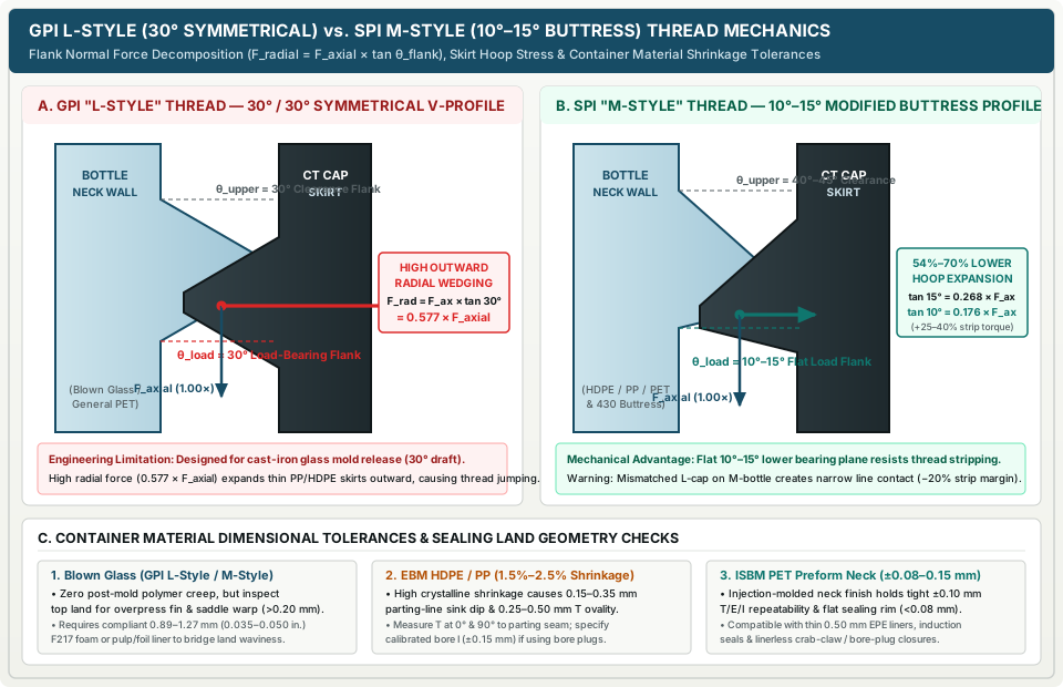
Flank force vector mechanics: why 30° L-style threads wedge thin plastic skirts outward
When a continuous thread closure is tightened to generate an axial liner clamping force (F_axial), that axial downward pull on the closure must be reacted upward by the lower load-bearing flank of the container thread pressing against the upper load-bearing flank of the closure thread. Neglecting friction angle offset for first-order normal force projection, a thread flank inclined at angle θ_load relative to the horizontal plane (perpendicular to the bottle axis) decomposes the axial clamping load F_axial into an outward radial wedging force (F_radial) pushing the closure skirt outward:
F_radial = F_axial × tan(θ_load)Comparing the two standard GPI/SPI profiles reveals why M-style buttress threads dominate modern thermoplastic closure design:
- GPI
L-StyleThread Profile (θ_load = 30°Lower Flank /θ_upper = 30°Clearance Flank):- Historical Origin: Standardized by
GPI / GCMIfor blown glass containers (Style 400L,410L,415L). In glass container blowing, cast-iron neck rings must open and release white-hot glass (~650–750°Cat the finish) without tearing or checking the glass thread root; a generous symmetrical30°draft angle on both flanks ensures clean mold release. - Radial Hoop Expansion Vector:
For everyF_radial (L-Style 30°) = F_axial × tan(30°) = 0.577 × F_axial100 N(22.5 lbf) of axial top load clamping the liner, anL-stylethread pushes the closure skirt radially outward with57.7 N(13.0 lbf) of hoop-expanding wedging force. On thin-walled polypropylene (PP) or high-density polyethylene (HDPE) closures, this0.577 × F_axialradial vector stretches the flexible skirt outward until the closure thread crests climb over the bottle thread crests (thread jumping / stripping) or initiate environmental stress cracking (ESCR) at high application torque.
- Historical Origin: Standardized by
- SPI
M-StyleModified Buttress Thread Profile (θ_load = 10°–15°Lower Flank /θ_upper = 40°–45°Clearance Flank):- Thermoplastic Optimization: Standardized by
SPI / ISBT(Style 400M,410M, and the430buttress series) specifically for injection-molded plastic closures and blow-molded plastic or precision glass necks. The lower load-bearing flank is flattened to10°to15°from horizontal, while the non-load-bearing upper clearance flank is steepened to40°to45°so the closure can still be stripped or unscrewed rapidly off injection-molding cores. - Radial Hoop Expansion Vector:
Flattening the load-bearing flank fromF_radial (M-Style 15°) = F_axial × tan(15°) = 0.268 × F_axial (53.6% reduction vs. L-Style) F_radial (M-Style 10°) = F_axial × tan(10°) = 0.176 × F_axial (69.5% reduction vs. L-Style)30°to15°cuts outward radial wedging force by53.6%(or by 69.5% at 10°), meaning anL-stylethread generates2.15×to3.28×more radial skirt expansion force than anM-stylethread at the exact same liner clamping load. Consequently,M-styleclosures achieve25% to 40%higher strip-out (jump) torque without requiring heavier closure wall thickness.
- Thermoplastic Optimization: Standardized by
| Thread Profile Attribute | GPI L-Style (30° Symmetrical V-Thread) |
SPI M-Style (10°–15° Modified Buttress) |
GPI 430 Series Deep Buttress Profile |
|---|---|---|---|
Lower Load-Bearing Flank (θ_load) |
30° from horizontal plane |
10° to 15° from horizontal plane |
7° to 10° heavy horizontal bearing shelf |
Upper Clearance Flank (θ_upper) |
30° from horizontal (60° included angle) |
40° to 45° from horizontal (asymmetric) |
45° steep upper clearance ramp |
Outward Radial Force (F_radial / F_axial) |
0.577 × F_axial (High radial skirt wedging) |
0.176 to 0.268 × F_axial (54%–70% lower wedging) |
0.123 to 0.176 × F_axial (Maximum top-load lock) |
Relative Strip-Out (Jump) Torque |
1.00× baseline (prone to jumping on thin PP skirts) |
1.25× to 1.40× higher strip-out resistance |
1.45× to 1.70× highest strip-out resistance |
| Primary Container & Closure Pairing | Legacy blown glass (Boston rounds, jars) + thick-wall PP or thermoset phenolic caps |
Extrusion-blow-molded HDPE/PP, ISBM PET, & modern glass + injection-molded PP/HDPE caps |
Chemical/acid glass & heavy HDPE jugs (28-430, 38-430) with integrated pouring lip |
Cross-Mating Risk (L vs. M Mismatch) |
Mating an M-style cap onto an L-style bottle (or vice versa) forces the 10°–15° flank to ride on the corner edge of the 30° flank (narrow line contact instead of planar bearing), reducing strip-out torque by 15%–25% and accelerating local polymer thread creep. |
Same rule: verify matching L or M suffix on both container and closure engineering drawings before releasing tooling. |
Cannot mate with 400/410/415 caps due to 16.5–25.4 mm tall pour-lip and drainback geometry. |
Container material shrinkage, ovality, and sealing land flatness checks
A drawing tolerance stackup only holds in production if the physical container neck conforms to geometric roundness and top-land flatness limits (Figure 2, Panel C):
- Blown Glass Containers (
Press-and-Blowvs.Blow-and-Blow):- Glass exhibits zero post-molding crystalline shrinkage or viscoelastic thread creep, making it a rigid mandrel for thread retention. However, glass finish rings are subject to three thermal-forming defects that must be screened at incoming inspection:
- Overpress (
Upward Rim Fin): A thin knife-edge of glass pushed upward along the inner rim of the sealing land (I), which slices through foil or pulp liners under capping top load. - Saddle / Warped Sealing Land: Circumferential waviness exceeding
0.20 mm(0.008 in.) across the top rim, requiring a thicker, compliant liner (0.89–1.27 mm/0.035–0.050 in.F217foam or pulp-backed foil) to bridge the gap. - Neck Ring Match Mismatch: Step offset
> 0.15 mmat the vertical mold parting seam across the threads or sealing rim.
- Overpress (
- Glass exhibits zero post-molding crystalline shrinkage or viscoelastic thread creep, making it a rigid mandrel for thread retention. However, glass finish rings are subject to three thermal-forming defects that must be screened at incoming inspection:
- Extrusion-Blow-Molded (
EBM)HDPEandPPContainers:- Semi-crystalline polyolefins (
HDPEcrystallinity65%–85%,PP50%–70%) undergo1.5% to 2.5%volumetric shrinkage during post-blow cooling. Because wall thickness is slightly heavier along the mold pinch/parting seam, differential cooling creates two systematic geometry shifts:- Parting-Line Sink Dip on the Sealing Land: A
0.15 to 0.35 mm(0.006–0.014 in.) local depression across the top sealing rim at the0°and180°mold parting line unless the neck is dome-trimmed or calibrated with a water-cooled blow pin. - Neck Ovality (
|T_0° - T_90°|): Thin-walled EBMHDPEnecks (28-400,38-400) commonly ovalize by0.25 to 0.50 mm(0.010–0.020 in.) between the parting-line diameter (T_0°) and the perpendicular diameter (T_90°). IfT_90°drops belowT_bottle,min, the closure threads strip along the minor axis first.
- Parting-Line Sink Dip on the Sealing Land: A
- Semi-crystalline polyolefins (
- Injection-Stretch-Blow-Molded (
ISBM)PETContainers:- Because an
ISBM PETbottle neck is injection-molded to its final dimensions during the preform stage (before the body is stretch-blown), the amorphous/semi-crystalline neck finish holds tight dimensional repeatability within±0.08 to ±0.15 mm(±0.003–0.006 in.) with top sealing land flatness inside<= 0.08 mm. This high geometric precision allowsPETnecks to run thinner0.50 mm(0.020 in.)EPEliners, single-piece induction seals, or linerless crab-claw (flexible top-land lip) and bore-plug closures.
- Because an
Takeaway: Specify M-style (10°–15° load flank) modified buttress threads whenever pairing thermoplastic PP or HDPE closures with plastic or custom glass containers, and measure EBM HDPE neck T dimensions across both 0° and 90° planes to catch parting-line ovality before it erodes ΔR_min.
Application torque, liner compression, and 24-hour torque retention decay
As detailed in TricorBraun’s Understanding Torque in Closure Applications and Drug Plastics’ Closure Torque Chart, rotational application torque (T_app) applied by a spindle wheel or servo chuck is merely an indirect mechanical input used to generate axial clamping force (F_axial, top load) across the sealing liner (Figure 3).
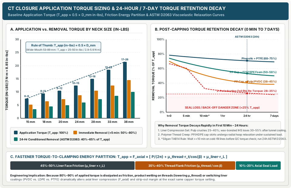
Fastener mechanics of a CT closure: why 80%–90% of torque goes to friction
Applying the classical helical screw-fastener torque-tension relationship (Motosh / Kellermann-Klein equation) to a pre-threaded continuous thread closure tightened onto a bottle neck relates input application torque (T_app) to resulting axial liner clamping force (F_axial):
T_app = F_axial × [ (P / (2 × π)) + (μ_thread × r_thread / cos(θ_load)) + (μ_liner × r_liner) ]Where:
P= axial thread lead pitch (2.12 mmfor12 TPI,3.18 mmfor8 TPI,4.23 mmfor6 TPI)μ_thread= coefficient of friction between container and closure thread flanks (typically 0.15–0.28dry plastic-on-plastic or plastic-on-glass)r_thread= mean thread contact radius (≈ (T + E) / 4)θ_load= load-bearing thread flank angle (30°forL-stylewherecos 30° = 0.866;10°–15°forM-stylewherecos 15° = 0.966)μ_liner= coefficient of friction between the rotating closure/liner face and the container top sealing land (typically 0.18–0.35)r_liner= mean sealing land radius (≈ (E + I) / 4)
Evaluating the three bracketed terms (Figure 3, Panel C) exposes a critical packaging engineering principle cited by TricorBraun:
- Liner Face Friction (
F_axial × μ_liner × r_liner): Consumes45% to 50%of total applied rotational torque. - Thread Flank Friction (
F_axial × μ_thread × r_thread / cos θ_load): Consumes35% to 40%of total applied torque (and increases by ~11.5% on a 30° L-style thread vs. a 15° M-style thread because 1 / cos 30° = 1.155 vs. 1 / cos 15° = 1.035). - Useful Axial Elastic Clamping Work (
F_axial × P / (2π)): Only10% to 20%of the torque delivered by the capping machine is actually converted into axial elastic/viscoelastic compression of the liner and axial tension in the closure skirt!
Because 80% to 90% of T_app is dissipated overcoming friction, any line change that alters μ_thread or μ_liner—such as liquid product splashing onto the bottle neck threads (acting as a lubricant that cuts μ_thread in half), switching from an unlubricated LDPE-faced liner to a slip-treated PTFE or Saran/PVDC facing, or changing closure resin slip additives (erucamide / oleamide bloom)—dramatically changes axial clamping force (F_axial) at the exact same capper torque setting. Specifically, lubricating the threads with product at a fixed T_app setting can double axial force F_axial, driving the closure straight past its strip-out (thread-jumping) limit.
Standard CT closure application and removal torque table (13 mm to 89 mm)
For dry, clean standard continuous thread closures lined with pulp, F217 / EPE foam, or foil liners, industry guidelines originally developed by the Plastics Industry Association (SPI) / Closure Manufacturers Association and published by Drug Plastics and TricorBraun establish three baseline sizing equations:
1. Recommended Application Torque:         T_app (in-lbs) ≈ 0.5 × Nominal Finish Diameter D (mm)   [±15% to ±20%]
2. Immediate Removal Torque (t <= 5 min):  T_rem,0        = 50% to 80% of T_app
3. 24-Hr Conditioned Removal (ASTM D2063): T_rem,24h      = 40% to 65% of T_app (Min floor >= 0.20–0.25 × D_mm)
(Unit conversion: 1 N·m = 8.8507 in-lbs, or 1 in-lb = 0.1130 N·m). The table below provides the complete diameter-by-diameter application, immediate removal, 24-hour conditioned removal, and minimum strip-out (jump) torque windows across standard 13 mm to 89 mm GPI/SPI finishes.
| Nominal GPI / SPI Finish Size & Common Codes | Recommended Application Torque T_app (in-lbs) |
Application Torque T_app (N·m) |
Immediate Removal Torque T_rem,0 (< 5 min, 50%–80%) |
24-Hr Conditioned Min Removal T_rem,24h (ASTM D2063) |
Minimum Strip-Out / Thread-Jump Torque (M-Style PP) |
|---|---|---|---|---|---|
13 mm – 15 mm (13-415, 13-425, 15-415, 15-425) |
6 – 9 in-lbs (nom 7.5 in-lbs) |
0.68 – 1.02 N·m |
3.5 – 7.0 in-lbs (0.40 – 0.79 N·m) |
>= 3.0 in-lbs (>= 0.34 N·m) |
> 14 – 18 in-lbs (> 1.58 – 2.03 N·m) |
18 mm (18-400, 18-410, 18-415, 18-425) |
8 – 11 in-lbs (nom 9.0 in-lbs) |
0.90 – 1.24 N·m |
4.5 – 8.5 in-lbs (0.51 – 0.96 N·m) |
>= 4.0 in-lbs (>= 0.45 N·m) |
> 18 – 24 in-lbs (> 2.03 – 2.71 N·m) |
20 mm (20-400, 20-410, 20-415) |
9 – 12 in-lbs (nom 10.0 in-lbs) |
1.02 – 1.36 N·m |
5.0 – 9.5 in-lbs (0.56 – 1.07 N·m) |
>= 4.5 in-lbs (>= 0.51 N·m) |
> 22 – 28 in-lbs (> 2.49 – 3.16 N·m) |
22 mm (22-400, 22-410, 22-415) |
10 – 13 in-lbs (nom 11.0 in-lbs) |
1.13 – 1.47 N·m |
5.5 – 10.5 in-lbs (0.62 – 1.19 N·m) |
>= 5.0 in-lbs (>= 0.56 N·m) |
> 25 – 32 in-lbs (> 2.82 – 3.62 N·m) |
24 mm (24-400, 24-410, 24-415) |
10 – 15 in-lbs (nom 12.0 in-lbs) |
1.13 – 1.69 N·m |
6.0 – 12.0 in-lbs (0.68 – 1.36 N·m) |
>= 5.0 in-lbs (>= 0.56 N·m) |
> 28 – 38 in-lbs (> 3.16 – 4.29 N·m) |
28 mm (28-400, 28-410, 28-415, 28-430) |
12 – 18 in-lbs (nom 14.5 in-lbs) |
1.36 – 2.03 N·m |
7.0 – 14.0 in-lbs (0.79 – 1.58 N·m) |
>= 6.0 in-lbs (>= 0.68 N·m) |
> 35 – 50 in-lbs (> 3.95 – 5.65 N·m) |
33 mm (33-400, 33-430) |
15 – 22 in-lbs (nom 17.5 in-lbs) |
1.69 – 2.49 N·m |
8.0 – 17.0 in-lbs (0.90 – 1.92 N·m) |
>= 7.0 in-lbs (>= 0.79 N·m) |
> 42 – 58 in-lbs (> 4.75 – 6.55 N·m) |
38 mm (38-400, 38-430) |
17 – 26 in-lbs (nom 20.0 in-lbs) |
1.92 – 2.94 N·m |
9.0 – 20.0 in-lbs (1.02 – 2.26 N·m) |
>= 8.0 in-lbs (>= 0.90 N·m) |
> 50 – 70 in-lbs (> 5.65 – 7.91 N·m) |
45 mm – 53 mm (45-400, 48-400, 53-400) |
21 – 30 in-lbs (nom 25.0 in-lbs) |
2.37 – 3.39 N·m |
11.0 – 23.0 in-lbs (1.24 – 2.60 N·m) |
>= 9.5 in-lbs (>= 1.07 N·m) |
> 65 – 90 in-lbs (> 7.34 – 10.17 N·m) |
70 mm – 89 mm (70-400, 89-400 Wide-Mouth) |
32 – 50 in-lbs (~0.5 × D_mm) |
3.62 – 5.65 N·m |
16.0 – 38.0 in-lbs (1.81 – 4.29 N·m) |
>= 13.0 – 18.0 in-lbs (>= 1.47 – 2.03 N·m) |
> 85 – 125 in-lbs (> 9.60 – 14.12 N·m) |
The three physical mechanisms of 24-hour to 7-day torque retention decay
Per ASTM D2063 (Standard Test Methods for Measurement of Torque Retention for Packages with Continuous Thread Closures), ASTM D3198, and Silgan Closures TAB14 Rev C, removal torque does not remain static after the container leaves the capper. As plotted in Figure 3, Panel B, a CT closure undergoes a steep exponential torque drop during the first 10 minutes to 24 hours (losing 20% to 45% of its immediate removal torque), followed by a gradual logarithmic plateau between 24 hours and 7 to 28 days (losing an additional 5% to 15%):
- Liner Viscoelastic Compression Set (
Primary Axial Relaxation Driver):- Pulpboard-Backed Liners (
Pulp/PVDC,Pulp/Tin Foil,Pulp/Wax,0.89–1.27 mm): Cellulosic pulp fibers crush plastically under top load, losing25% to 40%of their elastic rebound force within24 hours(retaining 38%–45% of T_appat24 hours). Pulp liners require application torque in the upper half of the standard window. - Co-Extruded Foamed Polyethylene (
F217 / EPE,0.50–1.00 mm): Three-ply low-density polyethylene (solid LDPE skin / closed-cell foamed PE core / solid LDPE skin) exhibits controlled viscoelastic relaxation (losing 15%–25% over 24 hoursand stabilizing at50%–58% of T_app) while maintaining elastic memory for repeated consumer resealing. - Two-Piece Induction Heat Seal (
IHS) Liners (Wax-Bonded Foil + Pulp/Foam Backing): As the capped container exits the induction sealing tunnel, the microcrystalline wax layer bonding the aluminum foil to the pulp backing melts and absorbs into the pulp board while radiant heat warms the plastic closure skirt. Once the package cools to ambient temperature, the closure liner has lost0.05–0.12 mmof effective thickness, causing removal torque to plummet by30% to 55%(often dropping to 28%–35% of T_app). High-speed bottling lines running two-piece induction seals must either validate elevated pre-induction application torque or install a post-induction re-torquing spindle station downstream of the induction coil.
- Pulpboard-Backed Liners (
- Thermoplastic Closure & Neck Thread Creep (
PP / HDPEvs.Thermoset Phenolic):- Polypropylene (
PP) andHDPEClosures: Because polyolefins operate above their amorphous glass-transition temperature (T_g ≈ -10°CforPP,-120°CforHDPE) at room temperature (20–25°C), sustained hoop tension in the closure skirt and bending stress in the thread teeth relax via viscoelastic polymer creep over24 hours. - Thermoset Phenolic (
Bakelite) or Urea Closures on Glass: Cross-linked thermoset resins exhibit virtually zero room-temperature polymer creep. When paired with a low-creepPTFE/rubberortin-foilliner on a glass bottle, phenolic caps retain68% to 75%ofT_appat7 days—which is why phenolic caps must not be over-torqued (excessive hoop stress cracks rigid thermoset skirts rather than stretching them).
- Polypropylene (
- Thermal Fill Contraction & The Silgan TAB14 10-Minute Cold-Fill Rule:
- When cold-filled plastic containers (
4–10°C) warm toward ambient warehouse temperature (20–25°C), the plastic neck expands radially (increasing T); conversely, when hot-filled containers (82–88°C) cool to ambient temperature, the plastic neck contracts (shrinking Tby0.15–0.25 mmand loosening thread contact). Per Silgan Closures TAB14 Rev C, quality inspectors on cold-fill lines must wait at least10 minutesafter capping before recording baseline quality-control removal torque and pull-up checks, and log exact capping and testing timestamps on a 4-post digital torque analyzer (Mark-10 TT01) as detailed in our cap torque testing protocol.
- When cold-filled plastic containers (
Rules of thumb for CT closure torque specification:
- Set your initial capper target with
0.5 × D_mm(in-lbs), then qualify at24 hours: A28-400or28-410cap should start line trials at14–15 in-lbs(1.58–1.69 N·m) application torque, targeting8–12 in-lbs(0.90–1.36 N·m) immediate removal (< 5 min) and>= 6.0 in-lbs(>= 0.68 N·m) conditioned removal after24 hoursat20–23°C(ASTM D2063).- Maintain a
>= 2.0× to 2.5×safety margin below strip-out torque: If your target application torque on a24-410closure is12 in-lbs, the paired bottle and closure must withstand at least25 to 30 in-lbson a motorized torque tester before jumping threads. If strip-out occurs below2.0 × T_app, auditΔR_minand verify whether anL-style30°flank is wedging the skirt open.
Takeaway: Separate application torque (T_app), immediate removal torque (T_rem,0 at < 5 min), and 24-hour conditioned removal torque (T_rem,24h per ASTM D2063) in every specification, and account for the 30%–55% post-cooling torque drop whenever induction heat sealing two-piece liners.
Continuous thread closure fit and torque troubleshooting matrix
When a bottling line experiences leakers, stripped caps, tilted closures, or warehouse back-off, use the 5-row engineering diagnostic matrix below to isolate whether the root cause lies in the container neck dimensions (T, E, I, H, S), the closure cavity tolerances (T_cap, E_cap, H_cap), the thread flank profile (L vs. M), or the capping/induction process.
| Observable Line or Warehouse Failure Mode | Primary Dimensional or Material Root Cause | Quantitative Gauge, Caliper & Torque Inspection Check | Corrective Engineering Action |
|---|---|---|---|
| 1. Skirt Bottoming-Out (Capper clutch trips at full torque and cap feels tight, but package leaks at top sealing rim) | Axial Skirt Interference (ΔH <= 0):• H_bottle,min - H_cap,max is smaller than compressed liner thickness (e.g., 410 cap applied to 400 bottle, or oversized bottle transfer bead / long closure skirt). |
• Coat bottle top sealing rim with Prussian blue / carbon transfer ink; torque cap to T_app; unscrew and check for 360° uninterrupted rim transfer ring.• Insert 0.25 mm (0.010 in.) feeler gauge between bottom edge of torqued cap skirt and bottle bead/shoulder. |
1. Verify matching GPI/SPI series code (400 vs. 410 vs. 415) on both drawings.2. Increase liner thickness ( e.g., from 0.020 in. [0.51 mm] to 0.035 in. [0.89 mm] F217) to raise seated cap elevation.3. Trim closure skirt cut-off length so ΔH_min >= 0.50–0.85 mm. |
| 2. Thread Jumping / Stripping (Closure overrides bottle threads and spins freely at or slightly above nominal application torque) | Insufficient Radial Overlap or 30° Wedging:• ΔR_min = (T_bottle,min - E_cap,max) / 2 < 0.25 mm (undersized/ovalized EBM bottle T + oversized cap E_cap).• L-style (30°) symmetrical flank expanding thin PP cap skirt (F_radial = 0.577 × F_axial).• Product wetting on threads lowering μ_thread and doubling F_axial at fixed T_app. |
• Measure bottle T at 0° and 90° to parting line and closure E_cap with caliper/CMM.• Run destructive strip-out torque test on Mark-10 TT01 ( must exceed 2.0–2.5 × T_app).• Inspect threads for liquid product contamination. |
1. Enforce ΔR_min >= 0.35 mm (>= 0.25 mm on <22 mm necks) across worst-case drawing limits.2. Upgrade paired tooling from L-style (30°) to M-style (10°–15° load flank) modified buttress profile.3. Eliminate filler nozzle drip onto neck threads or increase closure sidewall thickness. |
| 3. Cocked or Cross-Threaded Closure (Closure sits tilted on neck, catching on first thread turn with one side high) | Thread Start (S) or Pitch (TPI) Mismatch:• S_bottle < S_cap (first closure thread collides with bottle thread start before square entry).• 12 TPI (425) closure forced onto 8 TPI (400/415) neck.• Spindle wheel or chuck placer misaligned ( > 0.5 mm eccentricity) per our capping machine guide. |
• Measure container S and closure S_cap on optical comparator (target S_bottle,min >= S_cap,max + 0.25 mm).• Check thread pitch ( 6, 8, or 12 TPI) with pitch gauge.• Check cap chute/chuck squareness prior to first thread contact. |
1. Specify a feathered/tapered modified-buttress thread start lead-in with S_bottle >= 1.17 mm (on 18–38 mm sizes).2. Re-center capper starwheel pockets, neck guides, and gripper belts so cap enters coaxially within <= 0.25 mm. |
| 4. Bore Plug, Orifice Reducer, or Dip-Tube Binding (Insert pops up, cracks bottle neck, or blocks pump/dropper assembly) | Uncontrolled Inner Bore (I Dimension):• EBM parison blow-flash or glass overpress narrows internal bore below I_min.• Excessive internal neck wall taper prevents cylindrical bore plug from seating. |
• Pass calibrated Go / No-Go cylindrical plug gauge into neck bore I to full insert seating depth.• Check pump housing and pipette clearance per our lotion pump and dropper guides. |
1. Specify a calibrated/reamed neck bore (I tolerance ±0.15 mm) on EBM HDPE/PP bottles.2. Quarantine glass lots with inner-rim overpress fins. 3. Switch from a bore-plug seal to a top-land F217 foam or induction liner if I cannot be calibrated. |
5. Severe 24-Hour Warehouse Torque Back-Off (Removal torque drops below 25% of T_app or caps loosen during transit) |
Liner Compression Set & Post-Induction Shrinkage: • Two-piece wax-bonded induction liner loses 30%–55% top load after tunnel cooling without re-torquing.• High-creep plain pulp liner + PP skirt hoop relaxation.• Cold-fill thermal expansion / hot-fill cooling contraction. |
• Execute timed ASTM D2063 torque retention study at t = 5 min, 10 min, 24 h, and 7 d.• Run Silgan TAB14 Security Check: mark cap-to-bottle index, remove cap, re-apply to 2.0 in-lbs (0.23 N·m), and verify positive pull-up (+1/16 in.). |
1. Add a post-induction re-torquing spindle station downstream of the induction sealer (or switch to a 1-piece foam-backed IHS liner).2. Replace plain pulp liners with resilient co-extruded F217 / EPE foam.3. Enforce the TAB14 >= 10 min waiting rule on cold-fill lines before qualifying capper torque settings. |
Copyable GPI/SPI neck finish and CT closure qualification worksheet
Before approving new container molds, switching closure suppliers, or signing off on a capping line setup, packaging engineers and QA inspectors should execute and archive the 9-point dimensional and torque audit below alongside our paired drawing compatibility checklist and specimen torque test record.
| Audit Step & Parameter | Engineering Formula / Gauge Method | Acceptance Target (GPI / SPI & ASTM D2063) |
Sample Qualification Entry (28-410 HDPE + PP Cap) |
Blank Inspection Entry |
|---|---|---|---|---|
1. Finish Code (XX-YYY), Pitch & Flank Profile |
Verify paired container & closure engineering drawings (Rev level, TPI, and L-style 30° vs. M-style 10°–15°) |
100% match across nominal size, series (400/410/415/425/430), TPI, and L/M profile |
28-410 / 6 TPI (P = 4.23 mm) / M-Style Buttress (15° load) |
____-____ / ____ TPI / ____-Style |
2. Container Thread Crest OD (T_bottle at 0° & 90°) |
Digital vernier caliper (±0.01 mm) across mold parting seam (0°) and perpendicular (90°); compute ovality ` |
T_0° - T_90° | ` | Within drawing T limits (e.g., 27.33 ± 0.30 mm); neck ovality <= 0.25 mm (0.010 in.) |
3. Container Thread Root OD (E_bottle) & Depth h |
Knife-edge caliper or optical comparator at thread groove root; h_bottle = (T - E) / 2 |
Within drawing E limits (e.g., 24.94 ± 0.30 mm); single-side depth h ≈ 1.07–1.19 mm |
E_bottle = 24.98 mm (h_bottle = 1.17 mm — Pass) |
E_bottle = ____ mm (h = ____ mm) |
4. Closure Internal Diameters (E_cap & T_cap) |
Internal groove caliper / CMM scan vs. closure drawing limits; check ΔC_major = T_cap,min - T_bottle,max |
ΔC_major >= 0.15 mm & ΔC_minor >= 0.15 mm (0.006 in. min diametral root clearance) |
E_cap,max = 26.24 mm / T_cap,min = 27.82 mm (ΔC = +0.18 mm — Pass) |
E_cap,max = ____ / T_cap,min = ____ (ΔC = ____) |
5. Worst-Case Radial Thread Overlap (ΔR_min) |
ΔR_min = (T_bottle,min - E_cap,max) / 2 (plus measured sample pair ΔR_actual) |
>= 0.25–0.35 mm (13–22 mm necks); >= 0.35–0.50 mm (24–89 mm necks) |
ΔR_min = (27.03 - 26.24)/2 = 0.395 mm (Actual = 0.61 mm — Pass) |
ΔR_min = ____ mm (Actual = ____ mm) |
6. Axial Skirt-to-Shoulder Clearance (ΔH_min) |
ΔH_min = H_bottle,min - H_cap,max + feeler gauge under skirt at nominal T_app |
>= 0.50–0.85 mm uncompressed; >= 0.25 mm (0.010 in.) feeler gap when torqued |
17.40 - 16.55 = +0.85 mm (+0.61 mm torqued gap — Pass) |
ΔH_min = +____ mm (+____ mm torqued) |
7. Inner Bore ID (I_bottle) & Sealing Land Flatness |
Go / No-Go cylindrical plug gauge into bore I; optical flatness & parting-line sink check on top rim |
I >= I_min (>= 18.69 mm on 28-410); top land warp/sink <= 0.15–0.20 mm |
I = 18.92 mm Pass / Rim sink = 0.09 mm (360° ink seal — Pass) |
I = ____ mm / Rim flatness = ____ mm |
8. Thread Start (S) & Silgan TAB14 Pull-Up |
Measure S_bottle vs. S_cap; mark bottle thread start (0°/42°/78°) and log pull-up & 2 in-lbs security check |
S_bottle,min >= S_cap,max + 0.25 mm; uniform pull-up (±1/16 in.) & positive security |
S = 1.19 mm / Pull-up = +11/16 in. / Security = +1/16 in. — Pass |
S = ____ mm / Pull-up = ____ /16 in. |
9. Torque Curve (T_app, T_rem,0, T_rem,24h, T_strip) |
4-post digital torque tester (Mark-10 TT01) per ASTM D2063 at t <= 5 min and t = 24 hr (1,440 min) |
T_app ≈ 0.5 × D_mm (12–18 in-lbs on 28 mm); T_rem,24h = 40%–65% T_app; T_strip >= 2.2 × T_app |
T_app = 15.0 / T_rem,0 = 10.6 / T_rem,24h = 8.4 / T_strip = 41.5 in-lbs — Pass |
T_app: ____ / T_0: ____ / T_24h: ____ / Strip: ____ |
Technical basis and scope
This reference synthesizes published container and closure dimensional standards, fastener torque mechanics, and quality-control protocols from TricorBraun (Anatomy of a Bottle Neck Finish and Understanding Torque in Closure Applications), Berlin Packaging (Neck Finish Guide), Drug Plastics & Glass Co., Inc. (Neck Finishes Information Sheet and Closure Torque Chart), Paramount Global (Bottle Neck Thread Finish Guide — 400, 410, 415, 425, and 430 Series), Reliable Caps (Thread Profiles Selection Guide: L-Style vs. M-Style), SKS Bottle & Packaging (Cap and Neck Finishes), Silgan Closures Technical Assistance Bulletin 014 (TAB14 Revision C: Plastic Closure Quality Checks), and the Mark-10 Series TT01 Cap Torque Testers User’s Guide, alongside Glass Packaging Institute (GPI), Plastics Industry Association (SPI / ISBT), and ASTM D2063 / D3198 test methods.
For related qualification workflows across CMADC, return to the bottle neck finishes section, review paired drawing sign-off in bottle neck finish compatibility, check narrow-neck pipette interfaces in glass dropper bottle closure and neck finish specs, size actuator collars and dip tubes in lotion pump dispenser capping and dip-tube sizing, establish timed specimen logs in cap torque testing and tamper-evident band measurement, or compare spindle/chuck tightening against roll-on metal forming in capping machine selection and ROPP capper head adjustment.