Misadjusting a 4-roller ROPP capper head by even 0.25 mm of radial roller depth or 30 kgf of axial spring preload shears thin aluminum closure skirts, scuffs internal oxygen-barrier liners, and produces leakers or unbroken tamper-evident bands across an entire bottling run. Qualifying a roll on pilfer proof capping machine requires calibrating three separate mechanical force vectors in strict kinematic order: axial top-load compression (F_top = 110–250 kgf / 1,080–2,450 N) to seat the liner before any side roller contacts the shell, diametrically opposed thread-roller force (12–25 kgf / 118–245 N per roller) to cold-form the thread groove, and opposed pilfer-roller force (10–20 kgf / 98–196 N per roller) to crimp the perforated skirt beneath the bottle locking bead.
Where our capping machine selection guide contrasts pre-threaded spindle and chuck tighteners with metal-forming machines at the line-architecture level, and our wine bottle closure compatibility reference establishes why external screw-cap finishes seal on the top glass land rather than the internal neck bore, this field reference covers the mechanical setup, load-cell calibration, and failure-mode correction of the 4-roller sealing head itself.
| ROPP Head Parameter / Subsystem | Engineering Symbol | Standard Operating Window (18–38 mm Finishes) |
Primary Verification Instrument & Reference |
|---|---|---|---|
| Unthreaded Closure Shell Material | t_shell |
AA 8011 or AA 3105 (H14/H16 temper), 0.18–0.24 mm wall |
Micrometer & supplier alloy certificate (CETIE EC4.01 / EC4.02) |
| Stage 1: Axial Top-Load Plunger Force | F_top |
110–250 kgf (1,080–2,450 N) on glass; 65–105 kgf on rigid PET/HDPE |
Axial compression load cell at bottle lift top dead center (Zalkin Heads) |
| Plunger Over-Travel Stroke | Δz_stroke |
4.0–8.0 mm vertical spring deflection (absorbs ±0.8 to ±1.5 mm bottle height variance) |
Feel gauge / travel scale at maximum & minimum glass height lots |
| BVS Redraw Shell Elongation | ΔL_redraw |
~0.5 mm (±0.2 mm) axial length increase (1.5–1.7 mm top redraw step) |
Digital vernier caliper before vs. after capping (AWRI / CETIE Guide N°6) |
| Stage 2: Thread-Forming Rollers (2 Opposed) | F_thread |
12–25 kgf (118–245 N) radial force per roller (matched within ±0.5 kgf) |
Lateral load-cell gauge (Zalkin RCT Tool, 0–20 kgf ± 0.1 kgf) |
| Opposed Thread Roller Vertical Offset | Δz_pitch |
0.5 × P (1.59 mm on 8 TPI 28 mm finishes; 1.80–2.00 mm on BVS 30×60) |
Depth micrometer across 0° and 180° roller contact crests |
| Rolled Thread Groove Depth | d_groove |
0.65–0.95 mm radial indentation into glass thread root (E) |
Closure supplier Go / No-Go cylindrical thread ring gauge |
| Stage 3: Pilfer Tuck-Under Rollers (2 Opposed) | F_tuck |
10–20 kgf (98–196 N) radial force per roller (0.5–1.0 mm below locking bead) |
Lateral load-cell gauge (±0.1 kgf) & caliper check under bead |
| Head Spindle Revolutions per Bottle | N_rev |
2.5–4.0 full revolutions around neck during turret dwell arc (800–1,800 RPM) |
Tachometer & turret cam dwell angle calculation |
Two-Peak Removal Torque (28–30 mm Caps) |
T_slip / T_bridge |
8.0–18.0 in-lbs (0.90–2.03 N·m) at 24 hr (+10% target if tested < 5 min) |
Split-mandrel torque analyzer (Mecmesin / Mark-10 TT01) |
How a 4-roller ROPP capper head forms the seal and threads in two stages
Unlike pre-threaded plastic or phenolic screw closures—which arrive with molded internal threads and rely on spindle wheels or a torque-limiting chuck to apply rotational tightening torque (T_app)—an aluminum ROPP (Roll-On Pilfer-Proof) closure is fed into the capping chute as a smooth, unthreaded cylindrical aluminum shell. Standard shells are deep-drawn from AA 8011 (Fe-Si aluminum alloy) or AA 3105 (Al-Mn-Mg alloy) in H14 or H16 work-hardened temper at a nominal wall thickness of 0.18 to 0.24 mm, lined internally with a resilient sealing disc (expanded polyethylene [EPE] foam, PVDC/Saranex, Saran-Tin foil, or a molded LDPE/HDPE bore/land plug).
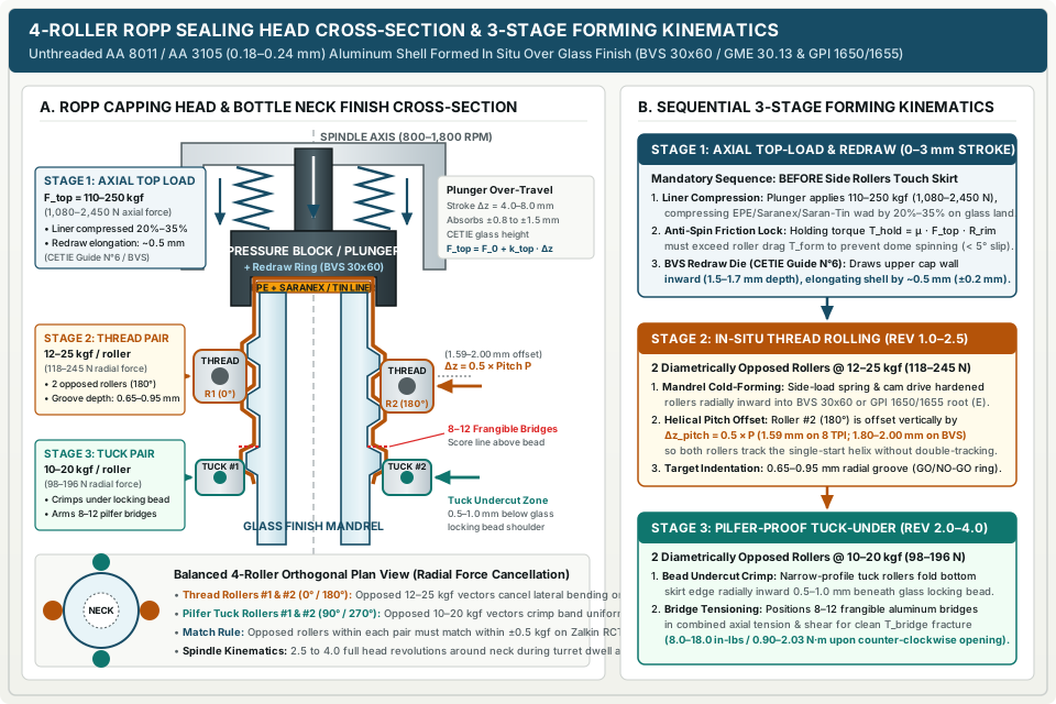
Because the unthreaded shell has no pre-formed helix, a roll on pilfer proof capping machine uses the container’s neck finish itself as the forming mandrel. As documented in Zalkin’s roll-on sealing head architecture and the Australian Wine Research Institute (AWRI) screw-cap application guide, the sealing head contains five core mechanical assemblies that must act in a strict axial-then-radial sequence:
- Pressure Block (Plunger & Redraw Die): Captures the unthreaded shell, centers it coaxially over the bottle finish, compresses the cap top and internal liner against the glass sealing land, and (on long-skirt wine finishes) redraws the upper outer wall of the aluminum shell.
- Top-Load Spring Pack (
1central coil or4matched circumferential top-load springs): Generates downward vertical clamping force (F_top) while deflecting through4.0 to 8.0 mmof axial stroke to absorb container height variations. - Side-Load Spring & Cam Follower Linkage: Translates vertical cam slide actuation into calibrated radial inward force across the four pivot arms as the head rotates around the bottle neck.
- Thread-Forming Rollers (
2diametrically opposed rollers at0°and180°): Trace the bottle’s external thread helix, cold-forming the smooth aluminum skirt into the thread root (dimension E). - Pilfer-Proof Tuck Rollers (
2diametrically opposed rollers at90°and270°): Roll the lower edge of the closure skirt radially inward underneath the bottle’s locking bead (transfer ring), arming the8 to 12frangible aluminum bridges above the undercut.
Stage 1: Axial top-load compression, frictional locking, and BVS redraw mechanics
As the bottle rises on a cam-actuated lift piston in a rotary turret (such as a Zalkin freestanding rotary ROPP capper running 3 to 24 heads at up to 60,000 bottles/hour), or as the pneumatic/mechanical head descends on a semi-automatic or inline frame (such as an Accutek AccuCapper ROPP machine), the internal pressure block contacts the closure dome first. During the initial 2.0 to 3.0 mm of plunger compression travel, the four side rollers remain retracted clear of the aluminum skirt.
The total axial top-load force (F_top, in N or kgf, where 1 kgf = 9.80665 N) delivered to the closure dome is governed by the head’s installed spring preload and linear spring rate:
F_top = F_preload + (k_top_total × Δz_stroke)
where:
F_preload= initial axial spring preload inside the head cartridge at the moment the pressure block contacts the cap (Norkgf)k_top_total= combined axial spring rate of the central coil or 4-spring pack (N/mmorkgf/mm, wherek_top_total = 4 × k_singlefor parallel 4-spring cartridges)Δz_stroke= vertical plunger over-travel after the cap seats on the bottle sealing rim (typically 4.0 to 8.0 mm), which compensates for glass container overall height tolerances (±0.8 to ±1.5 mmunder CETIE glass finish standards)
This axial force F_top performs three non-negotiable mechanical duties before side rollers touch the shell:
-
Hermetic Liner Compression (
σ_seal): As emphasized in our wine closure compatibility guide, the rolled thread merely holds the cap in place; the hermetic gas and liquid barrier is created exclusively by compressing the liner against the top rim (sealing land) of the glass finish. Compressing anEPEfoam core (1.5 to 2.0 mmuncompressed thickness) by20% to 35%requires a mean normal contact stressσ_sealacross the annular glass land areaA_rim:σ_seal = F_top / A_rim = (4 × F_top) / [π × (D_land_out² - D_land_in²)] -
Anti-Spin Frictional Locking (
T_hold > T_forming): When the four side rollers press radially into the aluminum skirt during Stage 2, their rolling and deformational drag exerts a tangential torque (T_forming) attempting to spin the cap shell on the bottle neck. To prevent dome spinning—which twists and tears the delicatePVDC(Saranex) orSaran-Tinbarrier facing against the glass rim—the static frictional holding torque (T_hold) generated byF_topmust exceedT_formingwith a safety factor of at least1.35:T_hold = (μ_block_cap + μ_liner_glass) × F_top × R_mean >= 1.35 × T_forming -
Circumferential Redraw & Shell Elongation (
BVS 30×60 mmWine Finishes): On long-skirt wine closures (CETIE GME 30.13 / EN 16293 BVS 30×60 mm), the pressure block incorporates an internal circumferential redraw ring (die). As detailed by AWRI and CETIE Bottling Guide N°6, once the liner is compressed against the top glass land, the redraw ring descends1.5 to 1.7 mmdown the upper outer wall of the cap. This action draws the aluminum tightly against the upper cylindrical side of the glass finish and produces a controlled axial shell elongation (ΔL_redraw) of approximately0.5 mm(±0.2 mm):ΔL_redraw = L_capped - L_uncapped ≈ 0.50 mm (±0.20 mm)
Stage 2 & Stage 3: Diametrically opposed thread rolling and pilfer-proof tucking
Only after the plunger has compressed through its initial 2.0 to 3.0 mm seating and redraw travel does the vertical slide cam drive the four roller arms radially inward. The head spindle rotates at 800 to 1,800 RPM, calibrated against the turret rotational speed so the head completes 2.5 to 4.0 full revolutions around the bottle neck while the rollers are engaged:
N_rev = (RPM_spindle / 60) × t_dwell = (RPM_spindle / RPM_turret) × (θ_dwell_deg / 360°)
The four rollers are mounted on a stainless-steel head body (such as the C.E. King M20183 4-roller ROPP capping head or Zalkin CA / Oppti.Cap series) in two orthogonal, diametrically opposed pairs (180° apart within each pair, 90° offset between pairs) so lateral bending loads cancel across the glass neck:
-
Pair 1 — Thread-Forming Rollers (
0°and180°,F_thread = 12–25 kgf/118–245 Nper roller): Two hardened, polished alloy-steel or titanium-nitride (TiN) coated rollers with a contoured outer rim radius matched to the bottle thread root (E). Because the bottle thread is a single-start helix with axial lead pitchP, the thread groove elevation at180°around the bottle neck is half a pitch lower than at0°. Therefore, Thread Roller #2 (180°) must be vertically offset by exactly half a thread pitch (Δz_pitch) relative to Thread Roller #1 (0°)—or ride on free-floating vertical follower pins:Δz_pitch = 0.5 × PFor a
28 mmGPI 1650orDIN PP28finish with8 threads per inch(P = 25.4 mm / 8 = 3.175 mm),Δz_pitch = 1.59 mm. For a30×60 mm BVSwine finish (P = 3.60 to 4.00 mm),Δz_pitch = 1.80 to 2.00 mm. -
Pair 2 — Pilfer-Proof Tuck-Under Rollers (
90°and270°,F_tuck = 10–20 kgf/98–196 Nper roller): Two narrower-profile lower rollers positioned0.5 to 1.0 mmbelow the underside of the glass locking bead. As the head completes its2.5 to 4.0revolutions, these rollers fold the lower rim of the perforated tamper-evident skirt radially inward under the locking shoulder. When the bottle is later unscrewed counter-clockwise, this tucked lip locks against the glass bead shoulder, forcing the8 to 12frangible aluminum bridges to snap in combined axial tension and torsional shear.
Rule of thumb: Never allow thread or tuck rollers to contact the aluminum skirt before the pressure block has compressed the top-load springs by at least
2.0 mm. Premature side-roller contact drags the unseated shell downward across the glass threads, causing premature bridge breakage at capper discharge or dome spinning that ruins liner oxygen-barrier integrity.
Takeaway: A 4-roller ROPP head is a two-stage axial-then-radial metal-forming die. Top-load pressure creates the hermetic rim seal and prevents shell rotation, while opposed, pitch-offset side rollers cold-form the threads and tamper-evident tuck without bending the bottle neck.
Target top-load and roller force settings by bottle neck finish
Mechanical force settings on a roll on pilfer proof capping machine scale directly with three package variables: aluminum shell alloy and thickness (AA 8011 vs. higher-yield AA 3105), liner compressibility (EPE foam vs. molded TPE/LDPE plug), and container column axial buckling resistance (glass vs. rigid PET/HDPE). Setting a pharmaceutical PP18 syrup head to sparkling-wine top loads crushes the thin 0.18 mm shell and chips the glass rim; conversely, running a carbonated MCA beverage finish at pharma spring tension results in immediate CO2 gas blow-off.
The table below compiles standard industrial engineering force windows across the five primary ROPP packaging sectors, synthesizing specifications from CETIE Metallic Screw Capping Guides N°2, N°6, N°9, and N°11, AWRI packaging guidelines, Zalkin head specifications, and Accutek ROPP capper documentation.
| Application Sector & Container Type | Standard Neck Finish Designation | Aluminum Shell Alloy & Wall (t_shell) |
Sealing Liner System & Barrier Rating | Axial Top-Load Force (F_top) |
Thread Roller Force (F_thread / Roller) |
Tuck Roller Force (F_tuck / Roller) |
Target 24-Hr Opening & Bridge Torque (T_slip / T_bridge) |
|---|---|---|---|---|---|---|---|
Pharma Oral Liquids & Dropper Vials (18–22 mm) |
DIN 6094 / EN 14798 PP18, PP20, PP22 (CETIE Guide N°2) |
AA 8011-H14/H16, 0.18–0.20 mm |
Molded LDPE bore/dropper plug or 1.5 mm EPE/PVDC wad |
110–140 kgf (1,080–1,375 N) |
12–16 kgf (118–157 N) |
10–14 kgf (98–137 N) |
5.0–11.0 in-lbs (0.56–1.24 N·m) |
Spirits, Aperitifs, Olive Oil & OTC (28 mm Short/Med Skirt) |
CETIE BVP / DIN PP28 (28×15, 28×18 mm) & GPI 1650 / 1655 |
AA 8011 or AA 3105-H14, 0.20–0.22 mm |
EPE + PVDC (Saranex) or PE-faced wad (1.6–2.0 mm) |
140–180 kgf (1,375–1,765 N) |
15–20 kgf (147–196 N) |
12–16 kgf (118–157 N) |
8.0–16.0 in-lbs (0.90–1.81 N·m) |
Still Table Wine (30×60 mm Long Skirt with Redraw) |
CETIE GME 30.13 / EN 16293 BVS 30×60 (CETIE Guide N°6) |
AA 3105 or AA 8011-H16, 0.21–0.23 mm deep-drawn |
Saranex (OTR 0.0001–0.001 cc O2/day) or Saran-Tin (0.00005–0.0005 cc O2/day) on EPE |
150–190 kgf (1,470–1,865 N) + ~0.5 mm redraw |
16–22 kgf (157–216 N) |
13–18 kgf (127–177 N) |
8.0–18.0 in-lbs (0.90–2.03 N·m; up to 2.80 N·m max on dry glass per AWRI) |
Sparkling Wine & Carbonated Drinks (28–30 mm Pressurized) |
CETIE MCA1 / MCA2 / MCA3 (28 mm) & BVS Pressurized (Guide N°9) |
AA 3105-H16 (high yield), 0.22–0.24 mm |
Molded PVC-free TPE/PE compound or high-density barrier liner (<= 4.0 bar CO2) |
180–250 kgf (1,765–2,450 N) |
18–25 kgf (177–245 N) |
15–20 kgf (147–196 N) |
10.0–18.0 in-lbs (1.13–2.03 N·m) + <= 4.0 bar pressure hold |
Rigid PET / HDPE Containers (24–28 mm Plastic Neck) |
PP28 / GPI 1650 molded PET or HDPE neck finish |
AA 8011-H14 (soft temper), 0.18–0.20 mm |
Foamed EPE (low durometer) or induction/conduction liner |
65–105 kgf (637–1,030 N; buckling limit < 115 kgf) |
10–14 kgf (98–137 N) |
8–12 kgf (78–118 N) |
6.0–12.0 in-lbs (0.68–1.36 N·m) |
Worked engineering calculation: Top-load spring preload, glass height tolerance, and sealing-land contact stress
To see how top-load spring kinematics and glass dimensional tolerances interact on a production turret, consider a rotary ROPP capper applying 30×60 mm BVS aluminum wine closures (CETIE GME 30.13 / Guide N°6) with an EPE + Saran-Tin liner onto 750 mL glass wine bottles. Before setting the head height on the turret column, confirm the paired bottle and closure dimensions using the verification steps in our bottle neck finish compatibility guide.
Given package and machine parameters (conditional calculation example for a 4-spring ROPP head on BVS 30×60 glass):
- Glass sealing rim (
land) outer diameter:D_land_out = 26.6 mm - Glass sealing rim (
land) inner bore diameter:D_land_in = 18.6 mm - Bottle overall height specification (
H_bottle):300.0 mm ± 1.2 mm(total height variationΔH_glass = 2.4 mmbetween shortest bottle298.8 mmand tallest bottle301.2 mm) - ROPP head top-load cartridge:
4matched parallel helical compression springs, each with individual spring ratek_single = 11.25 N/mm(1.147 kgf/mm), giving a combined pack ratek_top_total = 4 × 11.25 = 45.0 N/mm(4.589 kgf/mm) - Installed internal spring preload at zero plunger deflection (
Δz_stroke = 0 mm):F_preload = 1,380 N(140.7 kgf) - Nominal plunger over-travel stroke set on a mean-height (
300.0 mm) bottle at lift piston top dead center (TDC):Δz_nom = 5.5 mm
Step 1 — Calculate annular glass sealing-land area (A_rim):
A_rim = (π / 4) × (D_land_out² - D_land_in²) = 0.7854 × (26.6² - 18.6²) = 0.7854 × (707.56 - 345.96) = 284.0 mm²
Step 2 — Calculate axial top-load force (F_top) across nominal, minimum, and maximum bottle heights:
- On a nominal
300.0 mmbottle (Δz_stroke = 5.5 mm):F_top_nom = 1,380 N + (45.0 N/mm × 5.5 mm) = 1,380 + 247.5 = 1,627.5 N (166.0 kgf) - On the shortest
298.8 mmbottle (Δz_min = 5.5 - 1.2 = 4.3 mm):F_top_min = 1,380 N + (45.0 N/mm × 4.3 mm) = 1,380 + 193.5 = 1,573.5 N (160.5 kgf) - On the tallest
301.2 mmbottle (Δz_max = 5.5 + 1.2 = 6.7 mm):F_top_max = 1,380 N + (45.0 N/mm × 6.7 mm) = 1,380 + 301.5 = 1,681.5 N (171.5 kgf)
Because k_top_total is relatively flat (45.0 N/mm) while F_preload supplies 85% of the baseline force, the entire ±1.2 mm glass height tolerance shifts F_top only between 160.5 kgf and 171.5 kgf—remaining squarely inside the 150–190 kgf BVS wine operating window without bottoming out the 8.0 mm maximum plunger stroke.
Step 3 — Calculate normal sealing contact stress (σ_seal) and anti-spin holding torque (T_hold):
- Nominal sealing land contact stress:
σ_seal_nom = F_top_nom / A_rim = 1,627.5 N / 284.0 mm² = 5.73 MPa (57.3 bar) - Static frictional holding torque against dome spinning (using mean rim radius
R_mean = (26.6 + 18.6) / 4 = 11.3 mm = 0.0113 mand combined pressure-block + liner-to-glass friction coefficientμ_eff = 0.28):T_hold = μ_eff × F_top_min × R_mean = 0.28 × 1,573.5 N × 0.0113 m = 4.98 N·m (44.1 in-lbs)
Because 4.98 N·m of axial clamping friction is more than 2.5× the tangential drag torque exerted by the four side rollers (T_forming ≈ 1.6 to 2.0 N·m), the closure dome remains rotationally locked on the glass rim throughout thread and tuck forming.
Why rigid PET and HDPE containers require low-tension spring packs
As documented in Accutek’s ROPP capper engineering specifications, transitioning an ROPP capper from glass bottles to rigid PET or HDPE containers requires exchanging the high-tension glass top-load spring pack (140–250 kgf) for low-tension top-load springs (65–105 kgf / 637–1,030 N). Unsupported PET and HDPE container shoulders typically buckle axially or ovalize at the neck finish when downward plunger load exceeds 110 to 115 kgf (1,080 to 1,128 N). When running plastic containers with aluminum ROPP caps, pair 0.18–0.20 mm soft-temper AA 8011-H14 shells with low-durometer EPE liners so full liner sealing occurs below 100 kgf, and support the bottle beneath the neck transfer ring whenever container wall thickness permits.
Takeaway: Size the top-load spring preload and mid-stroke height so the shortest bottle in the tolerance lot receives enough axial force to prevent dome spinning (>= 150 kgf on BVS 30×60), while the tallest bottle retains at least 1.3 mm of spare plunger travel before mechanical bottoming.
Calibrating roller forces, thread depth, and two-peak opening torque
Because an ROPP sealing head forms threads radially rather than tightening a pre-threaded cap through a clutch, there is no direct application-torque dial on an ROPP capper. Opening torque and seal security are outputs of mechanical force calibration, dimensional thread depth, and post-capping liner relaxation. Qualifying a single-head or multi-head rotary capper requires four quantitative bench and line checks.
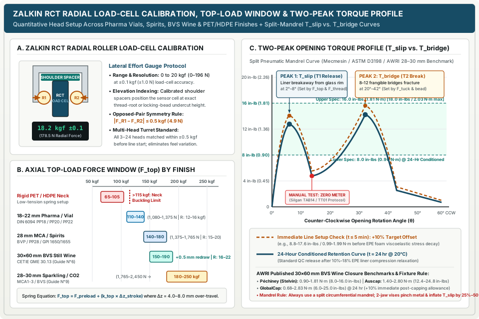
1. Lateral load-cell roller calibration (Zalkin RCT protocol)
Historically, line mechanics adjusted ROPP side-load springs by hand feel or by pulling a hook scale against the roller arm—a practice that introduces ±3 to ±5 kgf of head-to-head scatter across a 12- or 18-head turret. Modern bottling qualification replaces feel checks with an in-head radial load cell such as the Zalkin RCT (Roller Calibration Tool).
The RCT instrument inserts directly into the ROPP sealing head in place of a bottle neck, using precision shoulder spacers to position the strain-gauge load cell at the exact vertical elevation of either the thread-forming rollers or the pilfer tuck-under rollers:
-
Measurement range and accuracy: Measures radial inward effort from
0 to 20 kgf(0 to 196 N) with a calibrated resolution and accuracy of±0.1 kgf(±1.0 N). -
Opposed-pair symmetry rule: Within each head, Thread Roller #1 (
0°) and Thread Roller #2 (180°)—and separately Tuck Roller #1 (90°) and Tuck Roller #2 (270°)—must be balanced within±0.5 kgf(±4.9 N):|F_thread_R1 - F_thread_R2| <= 0.5 kgfand|F_tuck_T1 - F_tuck_T2| <= 0.5 kgf -
Eccentric inward stop vs. spring force: On industrial ROPP heads, the eccentric pin stop sets the maximum inward radial travel (
minimum diameter) of the roller arm, while the side-load spring nut sets the radial force (kgf) exerted when the roller contacts the incompressible glass thread root (E) or locking bead undercut. Always set the eccentric stop on a reference minimum-tolerance glass finish first so the roller cannot crush thin-walled glass, then calibrate the side-load spring to the targetkgfreading on theRCTgauge.
2. Dimensional verification: Go / No-Go thread ring gauge and 0.5 mm redraw check
Before destructive opening-torque tests are run, every capped specimen should pass two non-destructive dimensional gauges:
- Go / No-Go Cylindrical Thread Ring Gauge: Supplied by the closure manufacturer for the specific neck finish (
e.g., BVS 30×60,PP28, orGPI 1650), this double-ended ring gauge checks the outer envelope across the rolled thread grooves:- GO Side (
Maximum OD limit): Must slip freely over the rolled thread section under its own weight. If theGOring hangs up, the thread groove indentation (target 0.65–0.95 mm) is too shallow (under-rolled), risking thread stripping or pressure blow-off. - NO-GO Side (
Minimum OD limit): Must stop positively on the rolled thread section. If theNO-GOring passes over the cap, the thread rollers are adjusted too deep (over-rolled), thinning or shearing the0.20 mmaluminum wall and binding the cap on the glass threads.
- GO Side (
- Axial Redraw Elongation Check (
BVS 30×60 mmWine Finishes): Per AWRI and CETIE Guide N°6, measure uncapped shell length (L_0, nominally60.0 mm) and capped closure length (L_1) on the bottle using a digital vernier caliper or optical profile comparator. Confirm that the pressure-block redraw ring produces an axial shell elongation ofΔL_redraw = 0.5 mm ± 0.2 mm(0.30 to 0.70 mm). Elongation below0.30 mmindicates insufficient redraw compression; elongation exceeding0.80 mmover-stretches the skirt across the8–12frangible bridges.
3. Split-mandrel two-peak removal torque (T_slip vs. T_bridge) and 24-hour liner relaxation
As established in our cap torque testing protocol and our tamper-evident band measurement guide, recording a single “maximum opening torque” number on a pilfer-proof closure conflates two distinct mechanical events. Furthermore, Mecmesin’s engineering study on ROPP wine closure removal torque demonstrates a critical fixture rule for thin-walled (0.20–0.23 mm) aluminum caps: never grip an aluminum ROPP cap with a two-jaw V-block or over-tightened manual fingers. Point-contact clamping ovalizes the flexible aluminum shell and pinches its formed threads directly into the glass helix, artificially inflating measured removal torque by 25% to 50%.
Instead, use a split pneumatic or matched circumferential serrated mandrel lined with high-friction rubber on a digital or motorized torque analyzer (such as a Mark-10 Series TT01 or Mecmesin Vortex/Orbis system) mounted coaxially above a 4-post container grip (ASTM D3198 / ASTM D2063). During counter-clockwise rotation (typically 1.0 to 5.0 RPM on motorized testers), capture both peaks separately:
- Peak 1 — First-Opening Slip Torque (
T_slip, corresponding toT1at2°–8°CCW rotation): The torque required to break static friction between the compressed liner facing (Saranex / Saran-Tin / EPE) and the glass sealing land, plus initial thread flank release.T_slipis controlled primarily by Axial Top-Load Force (F_top), Redraw Depth, and Thread Roller Depth (F_thread). - Meter Zeroing Between Peaks (Manual Digital Testers): Following Silgan Closures Technical Assistance Bulletin 014 (TAB14 Rev C) and the Mark-10 TT01 operating manual, when using a manual torque meter without continuous curve plotting, stop rotation immediately upon observing first movement (
T_slip), re-zero the torque meter, and continue turning counter-clockwise until the bridges fracture to recordT_bridgecleanly. - Peak 2 — Pilfer Bridge-Break Torque (
T_bridge, corresponding toT2at20°–42°CCW rotation): As the cap rotates upward along the glass thread pitch (z = θ / 360° × P), vertical slack under the locking bead is taken up (around 0.4–0.8 mmof lift, or40°–70°total rotation to full fracture). The tucked bottom edge seats against the glass locking shoulder, driving torque to a second peak (T_bridge) where the8 to 12frangible aluminum bridges snap.T_bridgeis controlled by Tuck Roller Radial Force (F_tuck), Tuck Elevation under the Bead, and Closure Bridge Cross-Section.
Published removal-torque benchmarks and the +10% immediate-test relaxation rule
For standard 28–30 mm spirits and wine ROPP closures, general bottling acceptance targets span 8.0 to 18.0 in-lbs (0.90 to 2.03 N·m), where 1 N·m = 8.8507 in-lbs (1 in-lb = 0.112985 N·m). However, closure manufacturers specify distinct windows based on shell alloy, bridge geometry, and glass surface moisture. AWRI’s packaging operations guide publishes the following manufacturer-specific removal-torque windows for 30×60 mm BVS wine closures:
ROPP Closure Manufacturer / System (30×60 mm BVS) |
Conditioned 24-Hr Removal Torque (N·m) |
Conditioned 24-Hr Removal Torque (in-lbs) |
Immediate Line-Setup Target (t <= 5 min, +10% Offset) |
Critical Application & Conditioning Notes (AWRI) |
|---|---|---|---|---|
Péchiney (Stelvin 30×60 mm) |
0.90 – 1.81 N·m |
8.0 – 16.0 in-lbs |
0.99 – 1.99 N·m (8.8 – 17.6 in-lbs) |
Standard BVS wine specification (Saranex or Saran-Tin on EPE backing) |
Auscap (30×60 mm Long Skirt) |
1.40 – 2.80 N·m |
12.4 – 24.8 in-lbs |
1.54 – 3.08 N·m (13.6 – 27.3 in-lbs) |
Higher nominal bridge/release window; sensitive to wet vs. dry glass finish surface friction |
GlobalCap (30×60 mm Long Skirt) |
0.68 – 2.83 N·m |
6.0 – 25.0 in-lbs |
0.75 – 3.11 N·m (6.6 – 27.5 in-lbs) |
Explicitly specifies 24-hour conditioned test window and +10% offset for immediate post-capper testing |
Industry Standard 28 mm Spirits / BVP (PP28 / GPI 1650) |
0.90 – 1.81 N·m |
8.0 – 16.0 in-lbs |
0.99 – 1.99 N·m (8.8 – 17.6 in-lbs) |
Short/medium skirt (28×15 mm or 28×18 mm); verify T_slip and T_bridge separately |
Worked calculation: Converting immediate line-setup torque vs. 24-hour EPE liner relaxation
Why does GlobalCap (cited by AWRI) require a +10% higher torque reading when testing immediately off the capper (t <= 5 min) compared to t = 24 hours? Expanded polyethylene (EPE) foam cores exhibit viscoelastic stress decay (compression relaxation) during the first 24 hours under constant strain, reducing normal force on the glass land by 10% to 18%.
Formula:
T_immediate_target = 1.10 × T_24hr_spec
T_in_lbs = T_Nm × 8.8507
Worked example (conditional calculation for a Stelvin-type 30×60 mm BVS closure with a 24-hour specification of 0.90 to 1.81 N·m):
- Convert the
24-hourspecification limits fromN·mtoin-lbs:- Lower 24-hr limit:
T_24hr_min = 0.90 N·m × 8.8507 = 7.97 in-lbs (rounded to 8.0 in-lbs) - Upper 24-hr limit:
T_24hr_max = 1.81 N·m × 8.8507 = 16.02 in-lbs (rounded to 16.0 in-lbs) - Nominal 24-hr midpoint target:
T_24hr_mid = 1.355 N·m (12.0 in-lbs)
- Lower 24-hr limit:
- Calculate the immediate post-capping line setup window (
t <= 5 min, applying the+10%relaxation allowance):- Immediate minimum setup gate:
T_imm_min = 1.10 × 0.90 N·m = 0.99 N·m (8.8 in-lbs) - Immediate nominal setup target:
T_imm_mid = 1.10 × 1.355 N·m = 1.49 N·m (13.2 in-lbs) - Immediate maximum setup gate:
T_imm_max = 1.10 × 1.81 N·m = 1.99 N·m (17.6 in-lbs)
- Immediate minimum setup gate:
If a maintenance technician sets an ROPP head at line startup so immediate T_slip reads 8.1 in-lbs (0.91 N·m), the package appears to pass the 8.0 in-lbs minimum on the line—but after 24 hours of EPE liner relaxation (~11% decay), T_slip drops to 7.2 in-lbs (0.81 N·m), failing lot release.
4. Internal pressure and vacuum seal integrity verification (<= 0–4.0 bar)
Because a cap can display crisp threads and acceptable bridge-break torque while leaking across a scuffed or under-compressed liner, mechanical head qualification always concludes with an internal pressure or vacuum retention check:
- Still Wine, Spirits, and Pharmaceutical Syrups (
CETIE Guides N°2 & N°6): Pressurize conditioned capped bottles internally (or test in a calibrated vacuum chamber) to1.0 to 1.5 bar(14.5 to 21.8 psig) for5 minuteswith the neck submerged in water at20°C. Zero gas bubbles or liquid weepage may occur at the glass rim. - Sparkling Wine and Carbonated Beverages (
CETIE Guide N°9): Pierce the container sidewall or base with a calibratedCO2/hydraulic test needle and pressurize to4.0 bar(58.0 psig) at20°Cfor5 minutes. Confirm zero pressure decay, zero gas escape past the liner, and zero axial thread jump (cap dome creep <= 0.2 mm).
Takeaway: Calibrate side-load springs quantitatively with an in-head load cell (±0.1 kgf), verify thread envelope with a Go/No-Go ring gauge, and measure T_slip and T_bridge on a split mandrel using the +10% immediate-test offset to account for 24-hour EPE liner relaxation.
Aluminum ROPP cap sealing defect and troubleshooting matrix
When an inline vision system (such as a multi-camera turret inspector described by AWRI) or a quality-control torque check flags a defective aluminum ROPP cap sealing lot, operators must isolate the specific head assembly responsible rather than tightening all four rollers indiscriminately. In accordance with CETIE Guide N°11 (Metallic Screw Capping Defects — Identification and Correction), every physical closure defect maps to a specific stage of the head’s forming stroke.
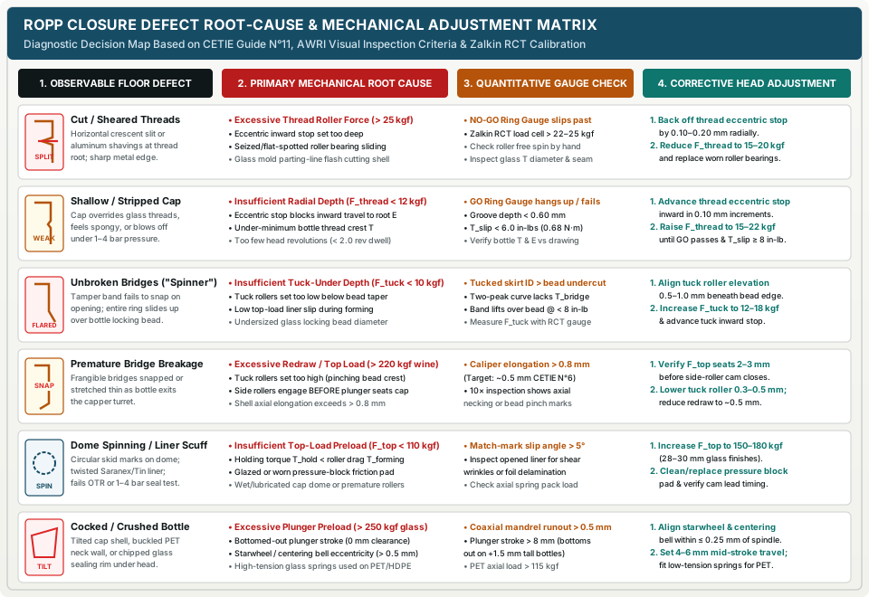
The 8-row engineering diagnostic matrix below pairs observable packaging-line defects with their primary mechanical root causes, quantitative verification checks, and exact corrective adjustments.
| Defect ID & Observable Symptom | Governing Stage & Primary Mechanical Root Causes | Quantitative Gauge / Torque Check | Step-by-Step Corrective Head Adjustment |
|---|---|---|---|
| 1. Cut, Sheared, or Split Aluminum Threads (Horizontal crescent slits or bright metal shavings along thread root; sharp edge) | Stage 2 (Thread Rollers): 1. Thread roller radial force F_thread > 25 kgf or inward eccentric stop set too deep.2. Seized, flat-spotted, or sharp-edged thread roller bearing sliding instead of rolling. 3. Glass finish mold parting-line flash or oversized T dimension cutting 0.20 mm aluminum from inside. |
• NO-GO ring gauge slips past formed threads. • Zalkin RCT lateral force reads > 22–25 kgf.• Inspect roller free rotation by hand and check glass parting seam with fingernail / optical comparator. |
1. Back off thread-roller eccentric inward stop by 0.10–0.20 mm.2. Reduce side-load spring tension to 15–20 kgf (16–22 kgf on BVS wine).3. Replace any roller with bearing play or rim scoring; quarantine glass lots with sharp parting-line flash. |
2. Shallow Threads or Stripped Cap (Cap feels spongy when twisted, overrides glass threads, or blows off under 1–4 bar pressure) |
Stage 2 (Thread Rollers): 1. Insufficient thread roller radial force ( F_thread < 12 kgf) or eccentric stop blocking inward travel.2. Undersized glass bottle thread crest diameter ( T below minimum drawing tolerance).3. Insufficient head revolutions ( N_rev < 2.0 rev) during turret dwell. |
• GO ring gauge hangs up / fails to pass over cap. • Rolled groove depth < 0.60 mm.• First-opening slip torque T_slip < 6.0 in-lbs (< 0.68 N·m).• Check bottle T and E dimensions against paired finish drawings. |
1. Advance thread-roller eccentric inward stop in 0.10 mm increments toward glass root E.2. Increase thread side-load spring force to 15–22 kgf until GO ring passes freely and T_slip reaches 8.0–16.0 in-lbs.3. Verify spindle drive ratio yields 2.5–4.0 revolutions per bottle. |
| 3. Unbroken Pilfer Bridges on Opening (“Spinner”) (Tamper band stays attached to cap shell and slides up over locking bead without snapping bridges) | Stage 3 (Tuck Rollers): 1. Insufficient tuck-under radial force ( F_tuck < 10 kgf) or inward stop too shallow, leaving bottom skirt flared.2. Tuck roller elevation set too low, rolling below the bead undercut where glass neck tapers inward. 3. Undersized glass locking-bead diameter or under-perforated closure bridge lot. |
• Measure tucked skirt ID underneath bead (must be < glass locking bead OD by >= 0.6 mm).• Motorized two-peak curve lacks T_bridge peak, or band slips past bead at < 8.0 in-lbs.• Check F_tuck with RCT load cell. |
1. Adjust tuck-roller vertical height to sit 0.5–1.0 mm directly beneath the glass locking bead undercut shoulder.2. Advance tuck eccentric stop inward and set F_tuck to 12–18 kgf.3. Confirm all 8–12 bridges snap cleanly and the detached ring remains on the bottle neck per tamper-band criteria. |
| 4. Premature Bridge Breakage During Capping (One or more frangible bridges are already snapped or stretched thin at capper discharge) | Stage 1 vs. Stage 2/3 Timing: 1. Excessive top-load force ( F_top > 220 kgf on still wine) or excessive redraw depth (> 2.0 mm) over-elongating shell (> 0.8 mm).2. Tuck rollers set too high, pinching aluminum against outer crest of glass locking bead and pulling band downward. 3. Side rollers engaging before pressure block fully seats cap on glass rim. |
• Measure capped shell axial elongation with caliper (exceeds > 0.80 mm vs. ~0.50 mm target).• Inspect broken bridge ends under 10× magnifier to distinguish axial tensile necking from radial pinch marks on bead crest. |
1. Verify cam timing so pressure block compresses 2.0–3.0 mm axially before side rollers touch skirt.2. Lower tuck-roller elevation by 0.3–0.5 mm to clear the locking bead crest.3. Reduce redraw ring shim depth or top-load spring preload so elongation holds at 0.50 ± 0.20 mm. |
| 5. Dome Spinning, Liner Scuffing, or Wrinkled Cap Top (Circular skid marks on cap dome; twisted/torn Saranex or Saran-Tin liner; fails pressure/OTR test) | Stage 1 (Top-Load Plunger): 1. Insufficient axial top-load force ( F_top < 110 kgf), allowing side-roller forming drag (T_forming) to spin cap on glass rim.2. Worn, glazed, or product-lubricated pressure-block friction pad / redraw die. 3. Side rollers closing too early during plunger descent. |
• Apply alignment witness mark across cap dome and bottle neck prior to capping: rotational slip angle exceeds > 5°.• Unscrew cap immediately and inspect liner face for circumferential shear wrinkles or foil delamination. |
1. Increase top-load spring preload to 150–180 kgf (28–30 mm glass) so T_hold >= 1.35 × T_forming.2. Clean or replace the urethane/steel pressure-block insert and degrease redraw ring. 3. Re-time cam slide to delay radial roller engagement. |
| 6. Cocked Cap, Crushed Bottle Neck, or Chipped Glass Rim (Cap sits tilted on finish, rigid PET/HDPE neck buckles, or glass rim cracks) | Stage 1 & Container Handling: 1. Excessive top-load force ( F_top > 250 kgf on glass, or > 115 kgf on PET/HDPE).2. Plunger stroke bottoming out ( 0 mm remaining travel) on tallest bottles in glass lot.3. Starwheel pocket or centering bell misaligned with head spindle ( > 0.5 mm eccentricity) or tilted chute pickup. |
• Check spindle-to-pocket coaxiality across all turret stations with a tapered alignment mandrel (target <= 0.25 mm runout).• Measure remaining plunger stroke at TDC on tallest bottle (must retain >= 1.3 mm clearance). |
1. Re-align starwheel pockets, neck guides, and centering bell within <= 0.25 mm of head axis; separate chute feed faults per our capping machine guide.2. Raise turret head column so nominal plunger stroke sits at 4.0–6.0 mm.3. Install low-tension top-load springs ( 65–105 kgf) when running PET/HDPE containers. |
7. Asymmetric Thread Depth or Double-Tracked Groove (Thread deep on one side and faint 180° opposite, or two overlapping helical tracks causing T_slip > 25 in-lbs) |
Stage 2 (Opposed Thread Pair): 1. Unbalanced side-load spring forces between Thread Roller #1 and #2 ( e.g., 19 kgf vs. 11 kgf).2. Incorrect vertical lead-pitch offset ( Δz_pitch != 0.5 × P) between 0° and 180° rollers, or seized vertical follower pin. |
• Measure both thread rollers individually with Zalkin RCT gauge (difference exceeds > 0.5 kgf).• Measure vertical elevation offset between opposed thread rollers with depth micrometer ( target 0.5 × P ± 0.05 mm). |
1. Calibrate both thread-roller side springs to identical radial force within ±0.5 kgf.2. Free and lubricate vertical roller follower pins, or reset fixed shim offset to 1.59 mm (8 TPI 28 mm) or 1.80–2.00 mm (BVS 30×60). |
| 8. High Cap / Unseated Closure Rim (Excessive gap between lower cap edge and bottle shoulder; zero liner compression impression) | Stage 1 & Redraw Ring: 1. Turret head column set too high ( plunger stroke < 2.0 mm at lift piston TDC).2. Oversized glass upper finish diameter binding inside BVS redraw ring before liner contacts rim. 3. Foreign cap liner (double-wadded shell) inside closure lot. |
• Open cap immediately and inspect EPE liner for uniform 360° glass rim impression (target 20%–35% compression).• Measure plunger compression deflection at TDC (< 2.0 mm indicates insufficient descent). |
1. Lower capping head column height so plunger compresses 4.0–6.0 mm at bottle lift TDC.2. Inspect glass finish upper sidewall diameter ( CETIE GME 30.13) and clean aluminum build-up from inside redraw die. |
Rules of thumb for line troubleshooting:
- Isolate the turret head before touching a wrench: On a multi-head rotary ROPP capper (
3 to 24heads), mark or track bottles by head number (Head #1throughHead #N). If a defect appears on only one station, adjust or rebuild that single head; if the defect appears across all stations simultaneously, investigate turret column height, incoming glass finish dimensions (T,E, locking bead, or bottle heightH), or closure shell/liner lot variation first.- Never increase thread-roller force to fix a leaking cap: Thread rollers form the retention groove (
Stage 2), not the hermetic top seal (Stage 1). Over-driving thread rollers to stop a top-rim leak merely cuts through the0.20 mmaluminum skirt while leaving theEPEliner under-compressed.
Takeaway: Diagnose ROPP defects by separating axial clamping faults (dome spin, leakers, crushed necks, over-elongation) from radial roller faults (sheared threads, shallow threads, unbroken spinner bands, double-tracking), and verify every adjustment with a Go/No-Go ring gauge and split-mandrel torque curve.
Copyable ROPP capping head setup and qualification record
To prevent operators from making unrecorded spring adjustments across shifts, packaging engineering teams should tie each capping head station to a traceable mechanical setup and lot-release log. Copy the record template below into your line qualification protocol alongside our specimen torque test record.
| Qualification Field | Engineering Target / Measurement Method | Recorded Setup Entry (Sample: BVS 30×60 Wine) |
Blank Line Entry |
|---|---|---|---|
| Line & Turret Head Station ID | Specific head number (e.g., Head #04 of 12); never average multi-head turrets into one setup value |
Rotary ROPP-02 / Head #04 (of 12) |
____ / Head #____ |
| Neck Finish Standard & Drawing Rev | Controlled glass/plastic finish code and approved supplier drawing revision (drawing check) | CETIE GME 30.13 (BVS 30×60) Rev D |
____ / Rev ____ |
| Closure Lot, Alloy & Liner Grade | Shell alloy/thickness (AA 8011 / 3105), bridge count (8–12), and liner barrier (Saranex / Saran-Tin / EPE) |
Lot #C-4092 / AA 3105 0.22 mm / Saran-Tin EPE |
Lot ____ / ____ mm / ____ |
Bottle Height Lot Range (H_bottle) |
Measured shortest and tallest container in lot (CETIE tolerance ±0.8 to ±1.5 mm) |
299.1 mm min – 300.9 mm max (300.0 nom) |
____ mm min – ____ mm max |
Stage 1: Top-Load Force (F_top) & Stroke |
Axial load cell reading at lift TDC (kgf / N) and plunger over-travel stroke (4.0–8.0 mm) |
166.0 kgf (1,628 N) @ 5.5 mm stroke |
____ kgf (____ N) @ ____ mm |
BVS Redraw Shell Elongation (ΔL_redraw) |
Capped closure length minus uncapped shell length via digital caliper (target 0.50 ± 0.20 mm) |
+0.52 mm (60.52 mm vs 60.00 mm) — Pass |
+____ mm — Pass / Fail |
| Dome Rotational Slip Check | Witness mark angular displacement between cap dome and glass neck after forming (target < 5°) |
1.5° rotational slip — Pass |
____° slip — Pass / Fail |
Stage 2: Thread Rollers #1 & #2 Force |
In-head lateral load cell (Zalkin RCT ±0.1 kgf); match #1 and #2 within <= 0.5 kgf |
R1 (0°): 18.2 kgf / R2 (180°): 18.0 kgf (178 N) |
R1: ____ kgf / R2: ____ kgf |
| Thread Roller Vertical Pitch Offset | Depth micrometer delta between 0° and 180° thread rollers (target 0.5 × P ± 0.05 mm) |
1.80 mm offset (P = 3.60 mm) — Pass |
____ mm offset — Pass / Fail |
| Go / No-Go Thread Depth Ring Gauge | GO side passes freely over rolled threads; NO-GO side stops on thread crest (0.65–0.95 mm groove) |
GO: Pass / NO-GO: Pass (0.82 mm groove) |
GO: ____ / NO-GO: ____ |
Stage 3: Tuck Rollers #1 & #2 Force |
In-head lateral load cell (10–20 kgf target) and vertical clearance below locking bead (0.5–1.0 mm) |
T1 (90°): 14.5 kgf / T2 (270°): 14.6 kgf @ -0.7 mm |
T1: ____ kgf / T2: ____ kgf |
| Post-Capping Conditioning Interval | Elapsed minutes (t_test - t_cap): immediate setup (<= 5 min, +10% target) vs. 24-hr relaxation (1,440 min) |
Immediate (3 min) & 24-Hr (1,440 min @ 20°C) |
____ min @ ____°C |
Peak 1: First-Opening Slip Torque (T_slip) |
Split-mandrel counter-clockwise breakaway peak (liner release at 2°–8°) |
14.1 in-lbs (1.59 N·m) imm / 12.8 in-lbs (1.45 N·m) 24h |
____ in-lbs (____ N·m) |
Peak 2: Bridge-Break Torque (T_bridge) |
Second peak after meter zero (or motorized curve Peak 2 at 20°–42°) + band retention on neck |
15.5 in-lbs (1.75 N·m) imm / 14.2 in-lbs (1.60 N·m) 24h — All 10 bridges broken, band retained |
____ in-lbs (____ N·m) — Bridges: ____ |
| Internal Pressure Seal Integrity Test | 1.0–1.5 bar (5 min still) or 4.0 bar (5 min sparkling per CETIE Guide N°9) |
1.5 bar for 5 min @ 20°C — Zero leak (Pass) |
____ bar for 5 min — ____ |
Technical basis and scope
This reference synthesizes primary mechanical and quality-control specifications from The Australian Wine Research Institute (AWRI) Packaging Operations Guide (Applying Screw Cap Closures), Zalkin Roll-On Sealing Capping Heads, the Zalkin RCT Roller Calibration Tool specification, Zalkin Freestanding Rotary Roll-On Cappers, CETIE Metallic Screw Capping Guides N°2, N°6, N°9, N°11 and Data Sheets EC4.01/EC4.02, Mecmesin ROPP Wine Closure Removal Torque analysis, Accutek AccuCapper ROPP Capper specifications, C.E. King M20183 4-Roller Stainless Steel ROPP Capping Head documentation, the Mark-10 Series TT01 Cap Torque Testers User’s Guide, and Silgan Closures Technical Assistance Bulletin 014 (TAB14 Revision C).
For related package qualification workflows across CMADC, return to the capping machinery section, compare bore stoppers and external screw caps in wine bottle closures and equipment compatibility, review machine architecture in capping machine selection, verify container-to-closure tolerances in bottle neck finish compatibility and GPI/SPI continuous thread closure dimensions, or consult the closure torque section and bottle neck finishes section.